

 Rules
Rules
by rdw777 Today at 9:00 am
» Fox .35 Modifications
by rdw777 Today at 8:51 am
» Jim Walkers FireBee - This is going to be fun
by rdw777 Today at 8:30 am
» Speed plane - Crispy but not too crispy
by rsv1cox Today at 6:43 am
» Roddie-Rigger.. a 2005 original design
by rsv1cox Today at 6:23 am
» Three (only one left) Cox .020 silencers for sale.
by GallopingGhostler Today at 5:12 am
» *Cox Engine of The Month* Submit your pictures! -May 2024-
by Admin Today at 2:38 am
» Post your Older books
by lla Yesterday at 6:34 pm
» S1 Ringmaster
by Onelife Yesterday at 8:40 am
» O&R 23 & Brown Jr
by getback Yesterday at 7:47 am
» Introducing our Cox .049 TD Engines
by MauricioB Yesterday at 2:31 am
» Jim Walker Firebaby
by rdw777 Tue Apr 30, 2024 4:16 pm


"Rodd-O-Gyro"
Page 1 of 3 • 1, 2, 3 ![]()

"Rodd-O-Gyro"
![]() roddie Fri Apr 10, 2015 8:47 pm
roddie Fri Apr 10, 2015 8:47 pm
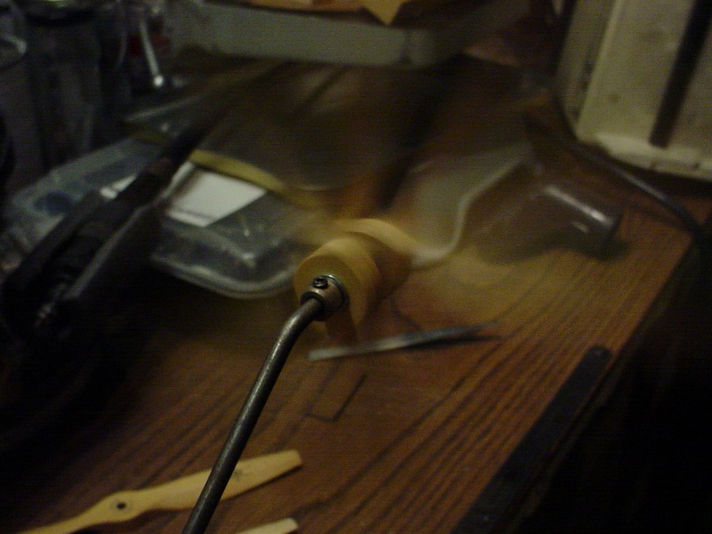
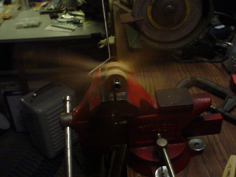
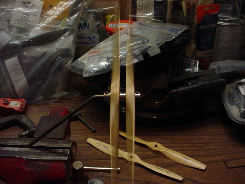
I've seen C/L model auto-gyros utilizing conventional propellers as rotor-blades.. so I'm trying to figure out how different configurations behave while free-wheeling in an airstream. I made a make-shift shaft with bushings/retainers etc. for the props to spin freely in the exhaust from a vacuum cleaner..
I happened to have several new 7 x 4 woodies in both; right and left hand.. (same brand/series-Zingers) to mess with. Besides.. its fun to spin things when you're bored.
Here's the counter-rotating set-up
What I'm try to figure out.. is whether conventional props used as rotors, would provide any lift.. or whether they'd only provide gyro-stabilization properties when tilted back into the airstream.
Here's a question.. would counter-rotating props spinning on the same shaft; lessen or cancel-out the gyroscopic effect? Engine thrust/prop-wash should have an effect on the rotor-head; "angle".. props pinned vs. freewheeling, facing into/away-from the air-steam, running R/H "pairs" vs. L/H pairs or counter-rotating.
Offsetting the rotor-shaft slightly outer-circle might provide line-tension?
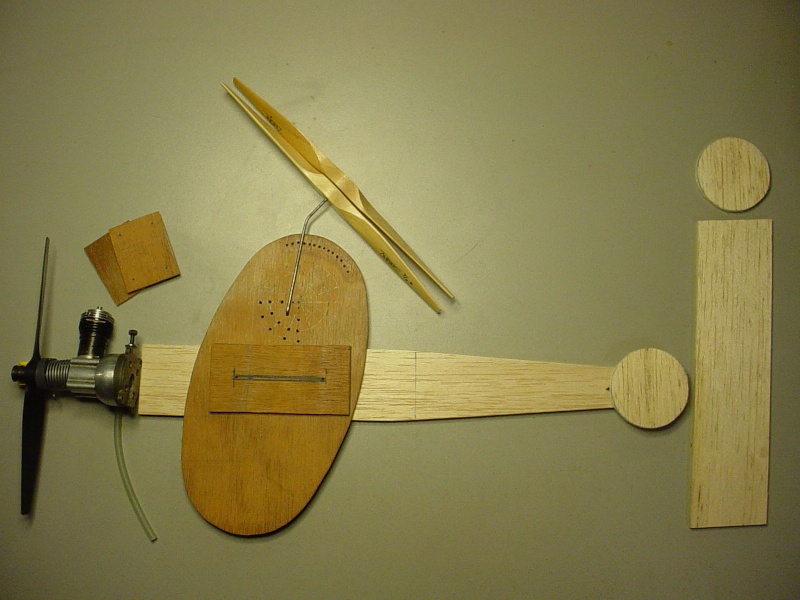
I drew up plans for a proposed 1/2A C/L auto-gyro to experiment with. It would have a Cox Babe Bee for power.. and a stub-wing to mount the bell-crank/lead-outs. Conventional profile airplane-fuse and tail-feathers.. tail-dragger gear. The rotor-shaft would be a much lighter 1/16" dia. music-wire rod with a short L-bend on the bottom. The rotor-shaft is a very simple one-piece design. It "pivots" on the bottom L-bend and is height-adjustable via a grid of holes in the plywood. A clamp sets back-tilt angle at the top. "Side-tilt" can be changed by using an alternate shaft bent "outward" at the top.

I haven't drawn fin/rudder yet.. and may go with dual-rudders on the stabilizer tips. Length w/engine is around 16" and the oval 3mm plywood "pod" which holds the stub-wing, rotor-head and main gear.. will slide fore/aft to trim the C of G.

roddie- Top Poster

- Posts : 8282
Join date : 2013-07-17
Age : 64
Location : N. Smithfield, Rhode Island -

fuse-blank and plywood rotor-plate cut
![]() roddie Sat Apr 11, 2015 11:26 am
roddie Sat Apr 11, 2015 11:26 am
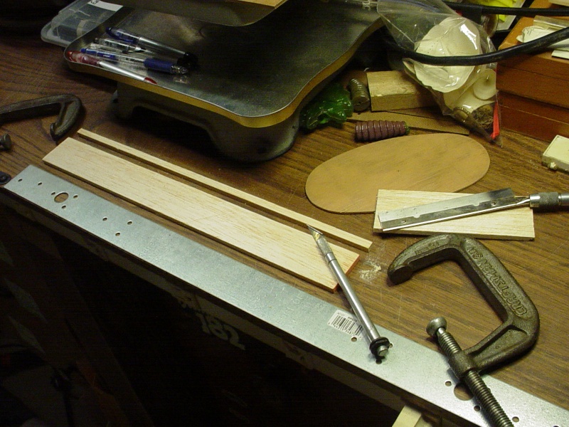
Next comes a conventional front radial-mount for a stock Babe Bee.
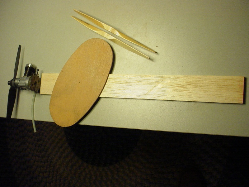
The rotor-shaft will have adjustable tilt-angles. I'm not sure if the prop-rotors should face down or up..
 Since they're "wind-driven" it will make a difference. I'm hoping to see some lifting properties as well as an outward roll force. I'm not sure where/how I'm going to mount the stub-wing yet. I had planned on going through a slot in the ply-oval, below the balsa fuse.. but I'm thinking closer to the centerline might be better. Who knows.. The rotor-angle should have an influence on the model's pitch in flight.. so the c of g might be somewhat variable; depending on the rotor tilt-angle.
roddie- Top Poster
- Posts : 8282
Join date : 2013-07-17
Age : 64
Location : N. Smithfield, Rhode Island -
Re: "Rodd-O-Gyro"
![]() pkrankow Sat Apr 11, 2015 11:58 am
pkrankow Sat Apr 11, 2015 11:58 am
I look forward to seeing what you end up with.
Phil

pkrankow- Top Poster
- Posts : 3025
Join date : 2012-10-02
Location : Ohio
Re: "Rodd-O-Gyro"
![]() rogermharris Sat Apr 11, 2015 12:15 pm
rogermharris Sat Apr 11, 2015 12:15 pm
rogermharris- Platinum Member

- Posts : 503
Join date : 2015-03-17
Age : 61
Location : Long Branch, New Jersey
Re: "Rodd-O-Gyro"
![]() roddie Sat Apr 11, 2015 12:53 pm
roddie Sat Apr 11, 2015 12:53 pm
pkrankow wrote:I think the 7x4 might be a little small. A 12x4 might be a better choice.
I look forward to seeing what you end up with.
Phil
You're probably correct Phil.. The shaft design will permit swapping-out longer blades and can be set higher for clearance if need be.
roddie- Top Poster
- Posts : 8282
Join date : 2013-07-17
Age : 64
Location : N. Smithfield, Rhode Island -
Re: "Rodd-O-Gyro"
![]() OVERLORD Sat Apr 11, 2015 3:59 pm
OVERLORD Sat Apr 11, 2015 3:59 pm
roddie wrote:What I'm try to figure out.. is whether conventional props used as rotors, would provide any lift.. or whether they'd only provide gyro-stabilization properties when tilted back into the airstream.
Here's a question.. would counter-rotating props spinning on the same shaft; lessen or cancel-out the gyroscopic effect? Engine thrust/prop-wash should have an effect on the rotor-head; "angle".. props pinned vs. freewheeling, facing into/away-from the air-steam, running R/H "pairs" vs. L/H pairs or counter-rotating.
I haven't drawn fin/rudder yet.. and may go with dual-rudders on the stabilizer tips. Length w/engine is around 16" and the oval 3mm plywood "pod" which holds the stub-wing, rotor-head and main gear.. will slide fore/aft to trim the C of G.
Hi Roddie,
Good to see you started the autogyro. The theory of turning rotors is a complicated matter. The rotor on an autogyro is driven by the airstram of the prop and the speed of the plane and could therefore be considered as a drag. However, the blades are air foil shaped and tend to lift as they move trough the air. You create the same flipping effect as with a helicopter. Only when the rotor turns at a great speed, it will act as a gyro and becomes a sort of disc. A fast turning rotor has to be achieved before launching. With 2 counter rotating props, logically thinking, the flipping effect would be non existing and the 2 props form 2 independent gyroscopes.
With the props laid out on your fuse and mast, isn't the fuse a bit too long? The Fernandez model is only about 35 cm long measured without the elevator and has a .09 engine. When your model is shorter, the rotor will be tilted more backwards before take off and will catch more Wind as well.
But tests will tell and the main thing is to have fun designing it, building it and overcome the mysteries or difficulties that you come across.
Lieven

OVERLORD- Diamond Member

- Posts : 1789
Join date : 2013-03-19
Age : 57
Location : Normandy, France
Re: "Rodd-O-Gyro"
![]() dinsdale Sun Apr 12, 2015 4:29 am
dinsdale Sun Apr 12, 2015 4:29 am
Yeah, I know it's a bit nit-picky, but you mean (in the setup you've shown) contra-rotating.roddie wrote:This would also allow testing a counter-rotating configuration.
Here's the counter-rotating set-up
As for lift from props used as rotors, I'd guess very little lift. The correct name for a helicopter is (as any military man here would know) actually a "rotary winged aircraft". The operative word there is winged. They are wings, not propeller blades. Instead of shoving the aircraft forwards at great speed to create airflow over the wings (and hence lift) they simply rotate the wings to create airflow (and hence lift). An auto-gyro simply combines the 2 processes. If you want to argue the point about wings vs propellers, take it up with an aeronautical engineer. There's a world of difference. A wing is designed to create lift, where-as a prop is designed to create thrust. As for contra-rotating rotors, there have been many of them, and quite successful.
https://www.google.com.au/search?q=contra+rotating+helicopter&source=lnms&tbm=isch&sa=X&ei=mz0qVev1DujCmAWxioCQDw&ved=0CAcQ_AUoAQ&biw=1289&bih=630
https://www.google.com.au/search?q=contra+rotating+vs+counter+rotating&biw=1289&bih=630&tbm=isch&tbo=u&source=univ&sa=X&ei=A0MqVcH8G6etmAX5s4DYCQ&ved=0CDMQsAQ

dinsdale- Account Deactivated by Owner
- Posts : 317
Join date : 2012-02-22
Re: "Rodd-O-Gyro"
![]() Oldenginerod Sun Apr 12, 2015 7:11 am
Oldenginerod Sun Apr 12, 2015 7:11 am
Am I right on this?
Rod.

Oldenginerod- Top Poster
- Posts : 3970
Join date : 2012-06-15
Age : 61
Location : Drouin, Victoria
Re: "Rodd-O-Gyro"
![]() getback Sun Apr 12, 2015 7:44 am
getback Sun Apr 12, 2015 7:44 am

getback- Top Poster


Posts : 10127
Join date : 2013-01-18
Age : 66
Location : julian , NC
Re: "Rodd-O-Gyro"
![]() roddie Sun Apr 12, 2015 9:32 am
roddie Sun Apr 12, 2015 9:32 am
getback wrote:I guess my Q would bee what do or are you wanting it to do or achieve ?? More lift ?
Well... Good question Eric. What I'm attempting to do is design this C/L A/G to prove or disprove my own curiosities by designing a "platform" that has a high degree of adjustability and options to try. Controlled flight is obviously the main objective.
Lieven made an interesting observation in the length of the fuse. Maybe it is too long. I'm afraid that if I make the tail-moment too short.. it may be really hard to flight-trim.
My theory on using standard propellers as rotor-blades.. or "rotary-wings" as Dinsdale mentioned, is that it "will" take force to turn them (in whatever configuration they're in..) and tilting them back into the air-stream/prop-blast will produce drag, as Lieven mentioned. The drag or resistance against forward movement is what I'm counting on. I may be able to control speed and lift.. by the ability to direct the force (sort of as a control-surface deflects) with the rotor's tilt-angle and height, which are both highly adjustable in my design.
I am very tempted to use a single inboard stub-wing (necessary for lead-outs..) mounted to the ply-oval. The oval holds the rotor assembly at the top.. and is attached to the inboard-side of the balsa fuse with a single machine-screw. I wanted to be able to adjust it's angle.. and fore/aft position. A stub-wing mounted to it.. could then be set for a positive angle of attack, to create lift. There comes two issues here; the lack-of outboard balance-weight.. and the need to mount the bell-crank on-center and on an L-bracket to keep it parallel for the elevator pushrod regardless of the stub-wing's angle. I'm hoping to create outward roll.. through an outward "tilt-angle" of the rotor-head and also the use of a 6 x 2 L/H Cox black prop on the Babe Bee.. which will induce an outward torque-roll.
Will any of this work? Who knows.. but I find enjoyment in experimenting.. which should be no surprise to many of you!
roddie- Top Poster
- Posts : 8282
Join date : 2013-07-17
Age : 64
Location : N. Smithfield, Rhode Island -
Re: "Rodd-O-Gyro"
![]() getback Sun Apr 12, 2015 12:29 pm
getback Sun Apr 12, 2015 12:29 pm

getback- Top Poster
-
Posts : 10127
Join date : 2013-01-18
Age : 66
Location : julian , NC
Re: "Rodd-O-Gyro"
![]() roddie Sun Apr 12, 2015 1:28 pm
roddie Sun Apr 12, 2015 1:28 pm
getback wrote: With prop is on the bottom seeing the prop blast from RH. prop is on the right ? and are you thinking of controlling the pitch while fling ?
Let's say that there was a thin solid disc atop the rotor-shaft, having the diameter of the rotor-blades. Tilted straight back would definitely provide lift during flight. Tilted back and "outward-circle" (or to the right-looking from the rear) would induce an outward rolling force from wind-deflection. "Spinning" rotor-blades probably to a much lesser degree. Tilt-position will be "fixed" on each experimental flight attempt.. but can be adjusted to a large degree for subsequent tests.
Pitch control is via a conventional stab./elevator. The main gear will be spread far enough to provide some stability for R.O.G launches.
roddie- Top Poster
- Posts : 8282
Join date : 2013-07-17
Age : 64
Location : N. Smithfield, Rhode Island -
Re: "Rodd-O-Gyro"
![]() ian1954 Mon Apr 13, 2015 5:56 am
ian1954 Mon Apr 13, 2015 5:56 am
I have not seen a control line autogyro but several RC ones, observed them being readied for flight and tested.
The blades were extremely light and have much more area than the propellers you are proposing. They were made from balsa with a carbon fibre leading edge.
The models I saw had adjustable pitch and the guy would let them run up as fast as possible before attempting take off. Lift off was fraught as the model wanted to keel over to one side. I saw several attempts on one before he got the corrections right. Same thing happens with a model helicopter - needs a bit of stick twiddling for a smooth take off.
In flight it looked simple and smooth but need constant throttle and pitch adjustment in and out of the wind and so the flight tended to be a bit up and down.
They had to be taken off and landed into the wind. As it approached the ground it would flip with the slightest of crosswinds.
I therefore the following comments for a CL version.
1. The model (as previously mentioned) should probably be quite short but it also needs to have a low centre of gravity.
2. The rotating blades generate lift. The lift is dependent on the speed the gyro slips through the air - I imagine it could be difficult getting a single settings when spinning it in a circle in and out of the wind.

ian1954- Diamond Member
- Posts : 2688
Join date : 2011-11-16
Age : 69
Location : England
Re: "Rodd-O-Gyro"
![]() roddie Tue Apr 14, 2015 7:22 am
roddie Tue Apr 14, 2015 7:22 am
ian1954 wrote:Another Roddie experiment.
I have not seen a control line autogyro but several RC ones, observed them being readied for flight and tested.
The blades were extremely light and have much more area than the propellers you are proposing. They were made from balsa with a carbon fibre leading edge.
The models I saw had adjustable pitch and the guy would let them run up as fast as possible before attempting take off. Lift off was fraught as the model wanted to keel over to one side. I saw several attempts on one before he got the corrections right. Same thing happens with a model helicopter - needs a bit of stick twiddling for a smooth take off.
In flight it looked simple and smooth but need constant throttle and pitch adjustment in and out of the wind and so the flight tended to be a bit up and down.
They had to be taken off and landed into the wind. As it approached the ground it would flip with the slightest of crosswinds.
I therefore the following comments for a CL version.
1. The model (as previously mentioned) should probably be quite short but it also needs to have a low centre of gravity.
2. The rotating blades generate lift. The lift is dependent on the speed the gyro slips through the air - I imagine it could be difficult getting a single settings when spinning it in a circle in and out of the wind.
Yes it is Ian! Experimenting is fun.. and I always learn something from it. It doesn't bother me if the results fall short of my expectations.
I did shorten-up the fuse to 12" on the plan.. and drew the stab., elevator and rudders. The oval on the drawing is 3mm plywood.. and will have approx. 2" (approx. 50mm) of fore/aft travel via a ply-reinforced slot in the fuse with a single #6 machine-screw/wing-nut to lock it's position. The elevator pushrod will be adjustable in length.

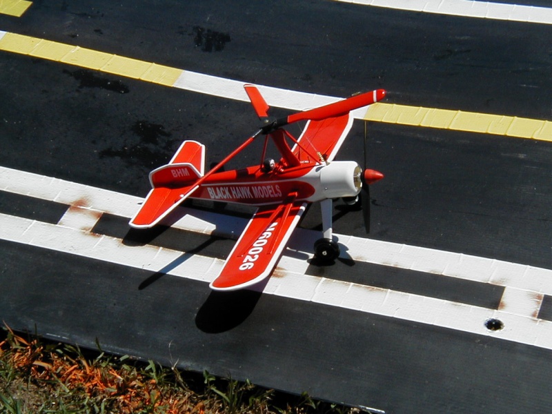
Lieven directed me to a model built by Javier Fernandez, called the Libelula.

Notice that Fernandez's model has a permanently-fixed rotor-angle.. with no adjustments for height/tilt. The rotor is comprised of two 11 x 4 conventional propellers which appear to be glued/pinned together. The engine he uses is an Enya .09 but it's prop-size is not stated.
I bent-up a couple of sample rotor-shafts.. to show how I plan to proceed in an adjustable tilt-angle; back and sideways. (they're a bit short.. but I used scrap 1/16" music-wire for mock-ups)
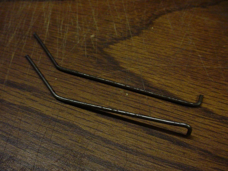
The short L-bend on the rod, locates in any one of a "series" of grid-holes drilled through the upper section of the 3mm plywood oval, just above the balsa fuse.. and will have some type of clamp for locking the tilt-angle at the top. I may choose to drill a radius-pattern of small holes near the top/rear edge of the oval.. and use tie-wire through them to retain the shaft. Has anyone had the patience to read this far?
To stub-wing.. or not to stub-wing.. that is a question. Most of the C/L auto-gyros I've seen so far, incorporate a wing or stub-wing.

I think that the Cox Apache and Fernandez models rely more on the rotors for lift.. but are less stable. The Blackhawk/Kellett design incorporates a larger wing area and span for more stability. This is where some challenging design considerations have to be addressed with my model.
EDIT: Furthermore.. the rotor on any single-rotor auto-gyro would induce a yaw.. wouldn't it? This is counteracted in a heli by using a vertical tail-rotor. Maybe a good experiment would be to use dual-rotors (R & L) set apart on stub-wings.. and running R/H pitch blades on one side.. and L/H pitch on the other? My question is; which side for which pitch.. or would it matter? This should in theory.. cancel-out the yaw effect.
roddie- Top Poster
- Posts : 8282
Join date : 2013-07-17
Age : 64
Location : N. Smithfield, Rhode Island -
Re: "Rodd-O-Gyro"
![]() fredvon4 Tue Apr 14, 2015 10:15 am
fredvon4 Tue Apr 14, 2015 10:15 am

fredvon4- Top Poster
-
Posts : 4002
Join date : 2011-08-26
Age : 68
Location : Lampasas Texas
Re: "Rodd-O-Gyro"
![]() getback Tue Apr 14, 2015 7:13 pm
getback Tue Apr 14, 2015 7:13 pm
 BEE Mark Built / Fly I am really wanting to do some of what he does , but for now the fun-ta-mintels
getback- Top Poster
-
Posts : 10127
Join date : 2013-01-18
Age : 66
Location : julian , NC
Re: "Rodd-O-Gyro"
![]() roddie Wed Apr 15, 2015 4:05 pm
roddie Wed Apr 15, 2015 4:05 pm

Still need to make an elevator and some sort of bellcrank-mount/lead-out arrangement.
roddie- Top Poster
- Posts : 8282
Join date : 2013-07-17
Age : 64
Location : N. Smithfield, Rhode Island -
pkrankow- Top Poster
- Posts : 3025
Join date : 2012-10-02
Location : Ohio
Re: "Rodd-O-Gyro"
![]() roddie Wed Apr 15, 2015 6:32 pm
roddie Wed Apr 15, 2015 6:32 pm
pkrankow wrote:Had fun with a drill there I see...
Phil
Well.. yea.. The central hole-pattern is for alternate locations to insert the short L-bend that's formed on the lower shaft, which will adjust shaft-height and some slight fore/aft variation. The radius hole-pattern at the top of the oval is for threading a tie-wire through, that loops around the shaft and twist-ties tight on the opposite side. This locks various back-tilt angles. Shown previously; was a shaft with a generous amount of rearward tilt bent-in.. but I also made a straight-shaft which will utilize the "lower-rear" holes on the radius pattern.

view from opposite side-below

Other alternate shafts will have side-tilt angles to test roll-induction.
The dual-rudder arrangement allows more clearance for testing a larger diameter rotor if need be. This allows a shorter tail-moment.. without a central-mounted fin/rudder getting in the way of the spinning rotor. (you'll see this design on many a/g's) I might need to design a more conventional constant-pitch rotor-blade.. but time will tell. My platform design should allow for that.. without having to change much else. The rotor-shaft can be bushed to suit different hub-sizes, and the rotor retention-system should work with differing rotors.
I'm building-in 2" of linear travel to the oval via a slot through a ply-reinforced outboard fuse-side. The inboard fuse-side and the oval's bearing surface will have coarse-grit sandpaper-faces for anti-slip. This provides some trim options as well.. (I hope..
roddie- Top Poster
- Posts : 8282
Join date : 2013-07-17
Age : 64
Location : N. Smithfield, Rhode Island -
Re: "Rodd-O-Gyro"
![]() RknRusty Thu Apr 16, 2015 2:22 pm
RknRusty Thu Apr 16, 2015 2:22 pm

Rusty
_________________
...and never Ever think about how good you are at something...
while you're doing it!
My Hot Rock & Blues Playlist

RknRusty- Rest In Peace

- Posts : 10869
Join date : 2011-08-10
Age : 68
Location : South Carolina, USA
Re: "Rodd-O-Gyro"
![]() roddie Thu Apr 16, 2015 10:01 pm
roddie Thu Apr 16, 2015 10:01 pm
RknRusty wrote:Roddie, I can add nothing, except that your imagination continues to astound me. And just to let you know I'm watching.
Rusty
Thanks Rusty.. I've got to get something started for the speed contest too.. and possibly another more conventional C/L design that I know will fly successfully..
roddie- Top Poster
- Posts : 8282
Join date : 2013-07-17
Age : 64
Location : N. Smithfield, Rhode Island -
Re: "Rodd-O-Gyro"
![]() duke.johnson Thu Apr 16, 2015 10:45 pm
duke.johnson Thu Apr 16, 2015 10:45 pm
roddieroddie wrote:RknRusty wrote:Roddie, I can add nothing, except that your imagination continues to astound me. And just to let you know I'm watching.
Rusty
Thanks Rusty.. I've got to get something started for the speed contest too.. and possibly another more conventional C/L design that I know will fly successfully..so I'm not too disappointed if the auto-gyro design doesn't work. Thanks to Ian.. I've got a few new engines to try out!
PM me your email and I'll send you a drawing of a pretty cool Cobra auto-gyro.
Duke

duke.johnson- Diamond Member
- Posts : 1734
Join date : 2012-11-05
Age : 52
Location : Rochester, Washington
Re: "Rodd-O-Gyro"
![]() duke.johnson Fri Apr 17, 2015 9:06 am
duke.johnson Fri Apr 17, 2015 9:06 am
You can post the drawings here on your thread if you like. John gave permission to share his drawings here on CEF. I just can't upload them from my office and alway forget by the time I get home. I've gotten ready to build this several times. I have a .35 size version to build someday too.
Duke
duke.johnson- Diamond Member
- Posts : 1734
Join date : 2012-11-05
Age : 52
Location : Rochester, Washington
Re: "Rodd-O-Gyro"
![]() roddie Fri Apr 17, 2015 10:17 am
roddie Fri Apr 17, 2015 10:17 am
duke.johnson wrote:Roddie
You can post the drawings here on your thread if you like. John gave permission to share his drawings here on CEF. I just can't upload them from my office and alway forget by the time I get home. I've gotten ready to build this several times. I have a .35 size version to build someday too.
Duke
Hi Duke, Thanks very much! I really like his design. I'll see if I can print/scan the pdf into a jpg file to upload. That's the only way I know how to do it. I have noted that his 1/2A C/L AH-1 design uses contra-rotating fixed-pitch rotor-blades. Very cool!
roddie- Top Poster
- Posts : 8282
Join date : 2013-07-17
Age : 64
Location : N. Smithfield, Rhode Island -
hinging and sanding
![]() roddie Fri Apr 17, 2015 8:10 pm
roddie Fri Apr 17, 2015 8:10 pm
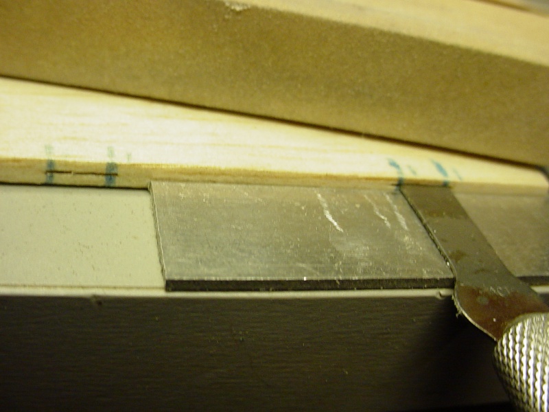
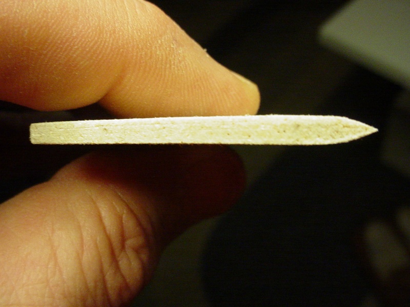
I'm working with 1/8" sheet balsa.. so I found a small piece of .060" aluminum to split the difference of the edges for slotting. Holding an x-acto blade down flat against the aluminum with my finger, I proceeded to "rock" the blade into the edge of the balsa. This works really well for centering the slot on the edge. I used Sig "Easy-Hinges" cut to 1/4"w. x 3/4" long.

Next comes the sanding... I dislike sanding...
Here's the profile of the stab's leading edge.

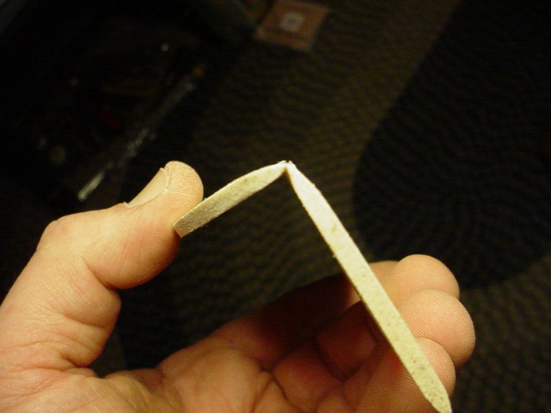
Here are the two surfaces with hinges fitted (not glued yet..) and an idea of how the dual-rudders will look.
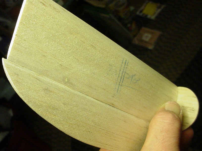
The gap between is minimal.. even at near 90 degrees deflection.
Sanding an even taper into the elevator's trailing edge radius will be tedious though.. but I like the way the radius looks. I also feel that it gives some exponential to control-inputs. I also feel that the dual rudder arrangement on the stab tips, allows consistent offset; unlike a single centralized offset rudder; which loses some of its effective-area when the elevator deflects.
roddie- Top Poster
- Posts : 8282
Join date : 2013-07-17
Age : 64
Location : N. Smithfield, Rhode Island -
Page 1 of 3 • 1, 2, 3 ![]()
» Auto- Gyro projects?
» The Cars are the Stars Contest.
» "Against all Odds" Rodd-E-Liminator vids
» Cars-Stars 2019 "Rodd-E-Liminator"