

 Rules
Rules
Log in
Search
Latest topics
» Roddie's flat-bottomed boat..by roddie Today at 10:11 am
» Project Cox .049 r/c & Citabrian Champion
by rdw777 Today at 8:14 am
» Jim Walkers FireBee - This is going to be fun
by rdw777 Today at 8:10 am
» Three -- sold out (making two more) Cox .010 Carburetors with wrench
by sosam117 Today at 8:07 am
» Revivng Some Childhood Classics
by getback Today at 7:31 am
» Fox .35 Modifications
by Ken Cook Today at 3:16 am
» Happy Anzac Day!
by Boats13 Yesterday at 11:03 pm
» Introducing our Cox .049 TD Engines
by getback Yesterday at 6:20 am
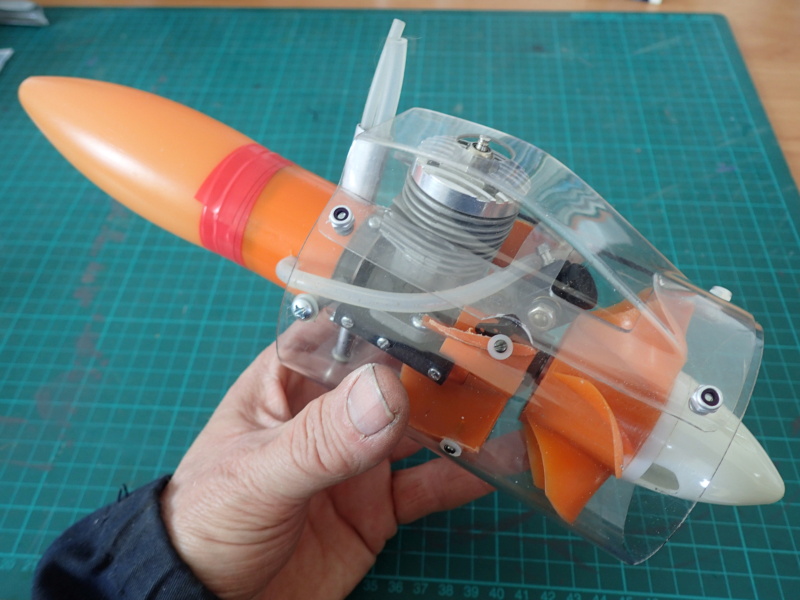
» Cox powered jet-pump for model Sprint Boat
by roddie Thu Apr 25, 2024 10:25 pm
» Micro Draco Gets to Fly on a Beautiful Morning.
by rdw777 Thu Apr 25, 2024 8:15 pm
» Jim Walker Firebaby
by rdw777 Thu Apr 25, 2024 8:06 pm
» Hydro-bat by Vic Smeed: engine probs
by GallopingGhostler Thu Apr 25, 2024 5:12 pm
Cox Engine of The Month

CEF Traveling Engine


Win This Engine!

Live on Patrol


Printed Circuit Boards
Page 1 of 1

Printed Circuit Boards
![]() roddie Sat Apr 01, 2017 12:12 pm
roddie Sat Apr 01, 2017 12:12 pm
I obtained some small boards from work which are totally flat with only "tracer-circuitry" running through them. The board-thickness is .067" (1.7mm).
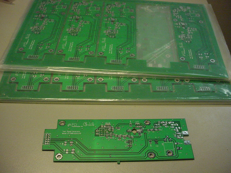
I'd read somewhere that this type of stock can be used for C/L bellcranks. It's very strong/rigid material.
I'm not sure how easy it is to cut through this stuff.. but it would be interesting to trace a bellcrank profile onto it.. and try using a scroll-saw to at least rough it out. A bearing is easily made from alloy-tube and some flat-washers.
Have any of you heard about or tried this?

roddie- Top Poster

- Posts : 8269
Join date : 2013-07-17
Age : 64
Location : N. Smithfield, Rhode Island -

Re: Printed Circuit Boards
![]() fredvon4 Sat Apr 01, 2017 12:48 pm
fredvon4 Sat Apr 01, 2017 12:48 pm
Other than weight, there is no reason the FREE stock you have won't work
What most guys use is the Raw circuit boards without any lead or copper traces....bread board stuff with or without a grid of through holes
You can cut control horns or even engine pads from your stock
It will also stack with thin skim of epoxy to make thicker and (caution*) sand down to thinner
at work look for some of the 1980s older BIG 18" x 18" (or larger) computer cards or main boards.... fairly thick but usually had several 4"x 5" areas totally un-populated--- just good big areas of material to cut to shapes
* use respirator!!!

fredvon4- Top Poster

Posts : 4001
Join date : 2011-08-26
Age : 68
Location : Lampasas Texas
Re: Printed Circuit Boards
![]() GallopingGhostler Sat Apr 01, 2017 3:12 pm
GallopingGhostler Sat Apr 01, 2017 3:12 pm
roddie wrote:I obtained some small boards from work which are totally flat with only "tracer-circuitry" running through them. The board-thickness is .067" (1.7mm).
I'd read somewhere that this type of stock can be used for C/L bellcranks. It's very strong/rigid material. I'm not sure how easy it is to cut through this stuff.. but it would be interesting to trace a bellcrank profile onto it.. and try using a scroll-saw to at least rough it out. A bearing is easily made from alloy-tube and some flat-washers. Have any of you heard about or tried this?
If it is a true fiberglass board it ought to work. If it is a material such as phenolic, then material is weaker and probably not worth trying. Give it a shot, tug, bend. If you have a CL model with bellcrank exposed, would be easy to test.
Back when I worked at McDonnell Douglas in the 1980's, we'd send minicomputer boards in for repair. They were multilayer trace (wiring levels embedded within the layers). If broken trace could not be jumpered, repairer would locate broken trace, mill down to the trace and repair it. Simpler boards might have 4 internal traces, but I heard as many as 10 layers. Due to expense of manufacturing multi-trace level boards, you'd only see this on more expensive equipment such as mini-computers, mainframes, aircraft avionics, etc.

GallopingGhostler- Top Poster

Posts : 5298
Join date : 2013-07-13
Age : 70
Location : Clovis NM or NFL KC Chiefs
Re: Printed Circuit Boards
![]() Jason_WI Sat Apr 01, 2017 5:28 pm
Jason_WI Sat Apr 01, 2017 5:28 pm
Cutting fiberglass FR4 circuit circuit boards is hard on blades. If you can get the round carbide blades for the scroll saw they might last longer. We have circuit boards at work that are close to 30 layers with blind and buried vias that are close to 1/4 inch thick. These cost $8000 before any parts are put on.
Jason_WI- Top Poster
-
Posts : 3123
Join date : 2011-10-09
Age : 48
Location : Neenah, WI
Re: Printed Circuit Boards
![]() GallopingGhostler Sat Apr 01, 2017 6:33 pm
GallopingGhostler Sat Apr 01, 2017 6:33 pm
Jason_WI wrote:Cutting fiberglass FR4 circuit circuit boards is hard on blades. If you can get the round carbide blades for the scroll saw they might last longer. We have circuit boards at work that are close to 30 layers with blind and buried vias that are close to 1/4 inch thick. These cost $8000 before any parts are put on.
Jason, thanks for the update. When I worked in the scientific computer aerospace industry 35 years ago, real men programmed in FORTRAN (and assembly) and quiche eaters wrote in PASCAL.
inf.ed.ac.uk: Real Programmers Don't Use PASCAL
We were still dealing with much stuff made in low and medium scale integrated circuits with a lot of discrete components. When I arrived at McDonnell Douglas in 1982, I remembered an old SEL hybrid analogue data acquisition computer for aircraft structural testing. It had 8 kb of ferrite bead core memory that the engineers and techs had upgraded with another bank of 8 or 16 kb static ram. It had just been removed from service (took up about 8 wall locker sized double cabinets). John, one of the techs would enter the boot loader via a line of binary toggle switches on the front panel, which then loaded the OS and application software from paper tape.
Our laboratory data computer was a then new Perkin Elmer 3240. I think it was 4 mips, with two 300 mb mulitplaten disk packs and 3 "high speed" 1600 bpi drives. It had a total of 16 mb dynamic ram. Each 4 mb board was about 2 feet square populated with 2kx1 or 4kx1 IC ram chips. High speed communication was via 1200 Baud modem. For tests we used smaller P-E 3220's (1 mip machine) and 3230's (2 mips I think) with 1 to 2 mb ram. 3230 was used for more demanding tests and had a higher capacity 30 mb hard disk the size of 2 shoe boxes.
Regarding cutting PC boards, I'd say yes if they are that thick. However, we're only talking material that is about 1/16" thick and small quantities, which a fine hacksaw blade (suitable to cutting EMT) would be able to cut.

GallopingGhostler- Top Poster
-
Posts : 5298
Join date : 2013-07-13
Age : 70
Location : Clovis NM or NFL KC Chiefs
» 3D printed RC plane videod by a drone
» 3D Printed .020 muffler
» Cox .020 Skycopter fuel tank replacement
» 3D Printed Cox Babe Bee
» 3D printed Pee Wee 0.020 tank extension?
» 3D Printed .020 muffler
» Cox .020 Skycopter fuel tank replacement
» 3D Printed Cox Babe Bee
» 3D printed Pee Wee 0.020 tank extension?
Page 1 of 1
Permissions in this forum:
You cannot reply to topics in this forum