

 Rules
Rules
Log in
Search
Latest topics
» Simple Glidersby rdw777 Today at 6:25 pm
» Foam hand kids glider converted to 0.049 CL
by rdw777 Today at 6:11 pm
» Weird search for a single comic from an old Mad Magazine
by Kim Today at 1:44 pm
» Scientific "Zipper" Build...Zipper Flys!.
by getback Today at 7:27 am
» Cox .049 Tee Dee engines back in stock (limited availablility)
by GallopingGhostler Today at 1:05 am
» Very off-topic.........Time passes and not always for the best......
by rsv1cox Yesterday at 2:47 pm
» Golden Bee basic running problem
by 944_Jim Yesterday at 12:44 pm
» Roddie-Rigger.. a 2005 original design
by roddie Wed Jul 24, 2024 11:48 pm
» Jim Walker Bonanza etc.
by rsv1cox Wed Jul 24, 2024 6:30 pm
» Throttles for Cox Tee Dee .049 / .020 / .010 engines --- videos
by sosam117 Wed Jul 24, 2024 8:54 am
» Introducing our Cox .049 TD Engines
by Admin Tue Jul 23, 2024 2:00 am
» Project Cox .049 r/c & Citabrian Champion
by getback Mon Jul 22, 2024 4:14 pm
Cox Engine of The Month
July-2024
robot797's
"ULTIMITE COX 010: it has a clutch, E starter, throttle, exhaust, aluminum tank, aluminum venturi, gearbox with forward and reverse, and now its on a custom drawn and printed stand"

PAST WINNERS
robot797's
"ULTIMITE COX 010: it has a clutch, E starter, throttle, exhaust, aluminum tank, aluminum venturi, gearbox with forward and reverse, and now its on a custom drawn and printed stand"
PAST WINNERS
CEF Traveling Engine

Win This Engine!

Live on Patrol


A Quick Aside
Page 1 of 1

A Quick Aside
![]() batjac Fri Dec 08, 2017 4:27 am
batjac Fri Dec 08, 2017 4:27 am
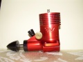
I’m working on another super-secret project, but I couldn’t stop thinking about Kari’s suggestion about a crankcase with mounting lugs for a postage stamp backplate. Mark B. posted a picture of an engine mount with mounting lugs made from a piece of 1/8” aluminum T extrusion. It works well, and looks good. But the T shaped extrusion isn’t something that you can just run out and buy unless you have a metals superstore around. And it’s not exactly cheap. I had an idea that could be done with materials you can get anywhere, and most guys probably have in their garage anyway, so I decided to take a break from the replic, I mean secret project, and make up the mount real quick.
I figured that even though the beam mount from T-section was nice, it wasn’t worth it to me for the cost of materials to order online. In my workroom I have plenty of aluminum angle in 1/8” and 1/16” of various sizes. I’d image most of us guys have some in the garage or workroom. So, I thought it could be cut and shaped very quickly into a bed mount for the postage stamp backplates. I figured 1/8” is overkill, so I went with some 1/16”x1” angle.
I bought four postage stamp backplates off of eBay a couple of months ago just to get the fine needle valve assemblies. With shipping, they came out to about four bucks for each fine NVA. MUCH cheaper than the fine needle assemblies Texas Timers sells. I pulled the NVAs from the postage stamp backplates and then threw the backplates in one of my spares boxes. I dug one back out for this test.

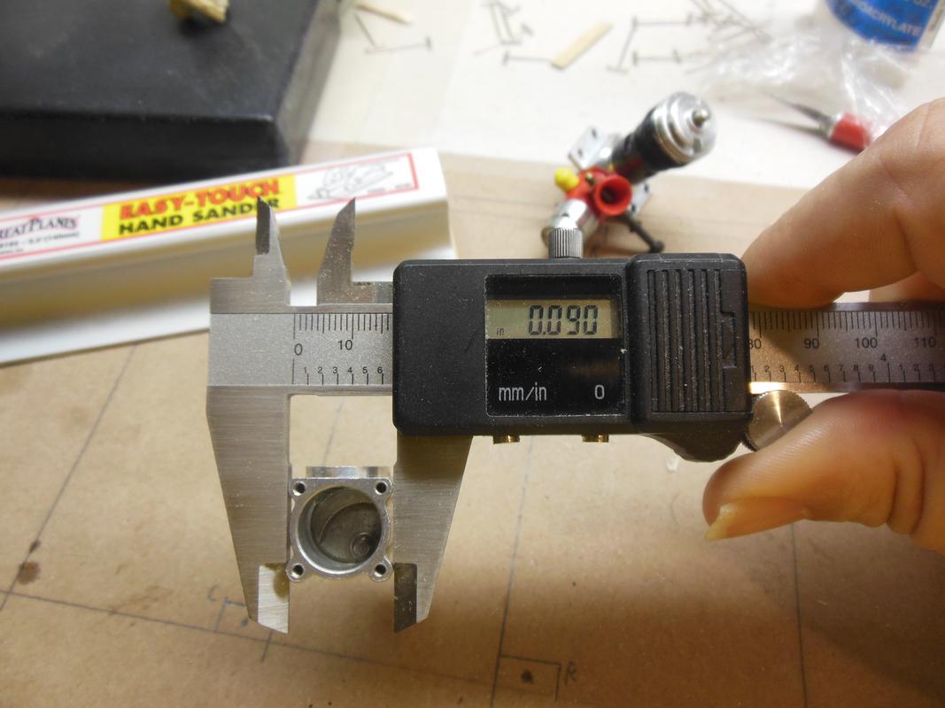
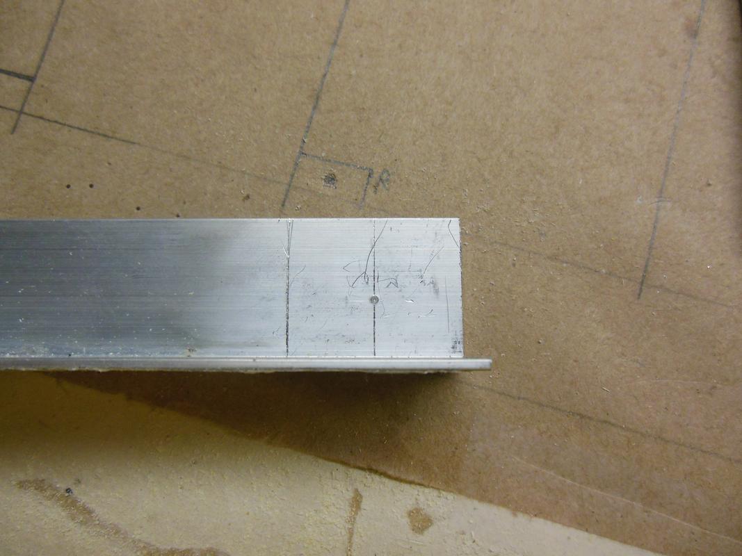
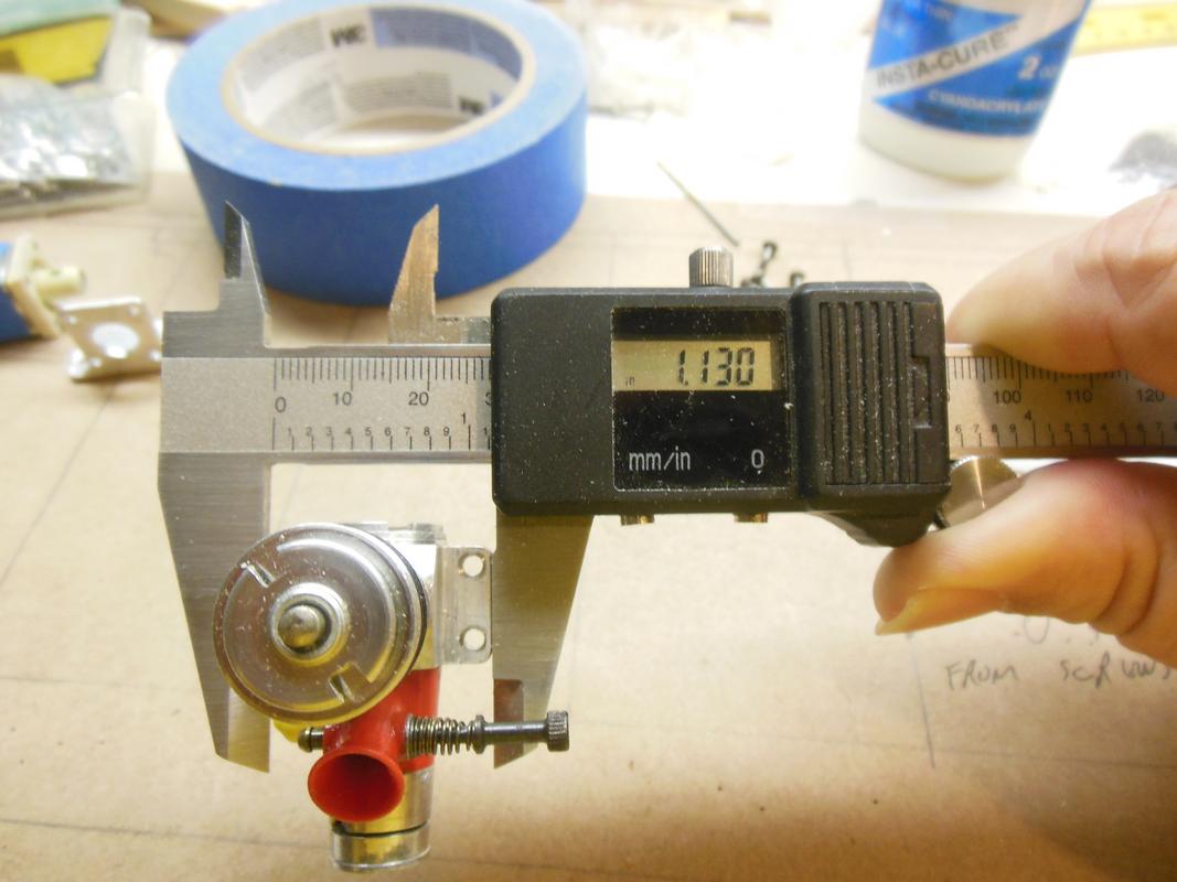
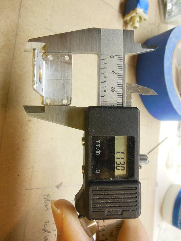
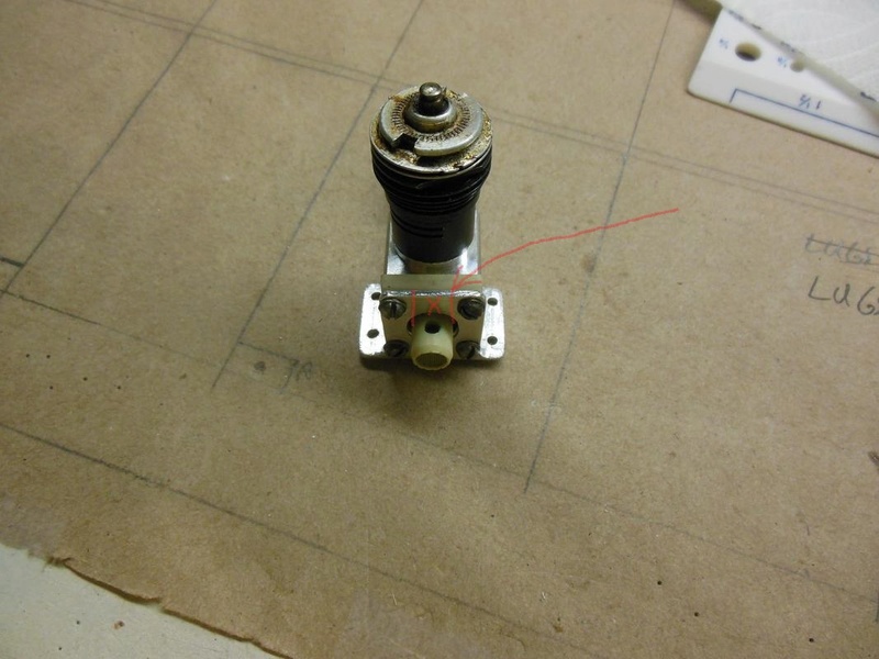
To make this thing more useful, I decided that it had to fit the mounting holes of a Medallion or a TeeDee. The first thing I did was measure the width of a Medallion .049 case at the lugs, and then measure the width of a regular extruded reedie case. I zeroed my calipers on the Medallion case so I could see how much wider the extruded case was. The reedie case is 0.090” wider than the Medallion case. I don’t know why the image hosting site rotated the Medallion image by 90 degrees, but it won’t let me correct the rotation.

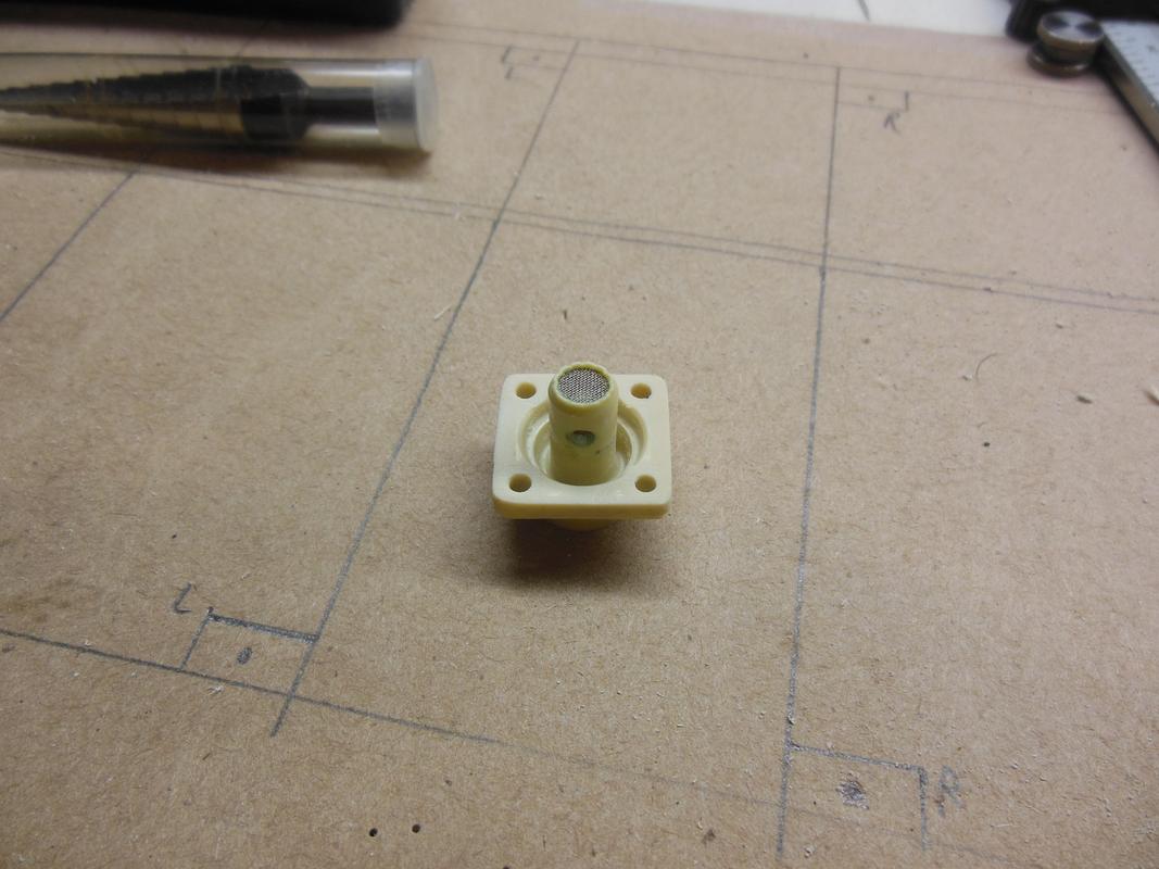
Then I trimmed off the excess plastic from the backplate and filed it smooth.
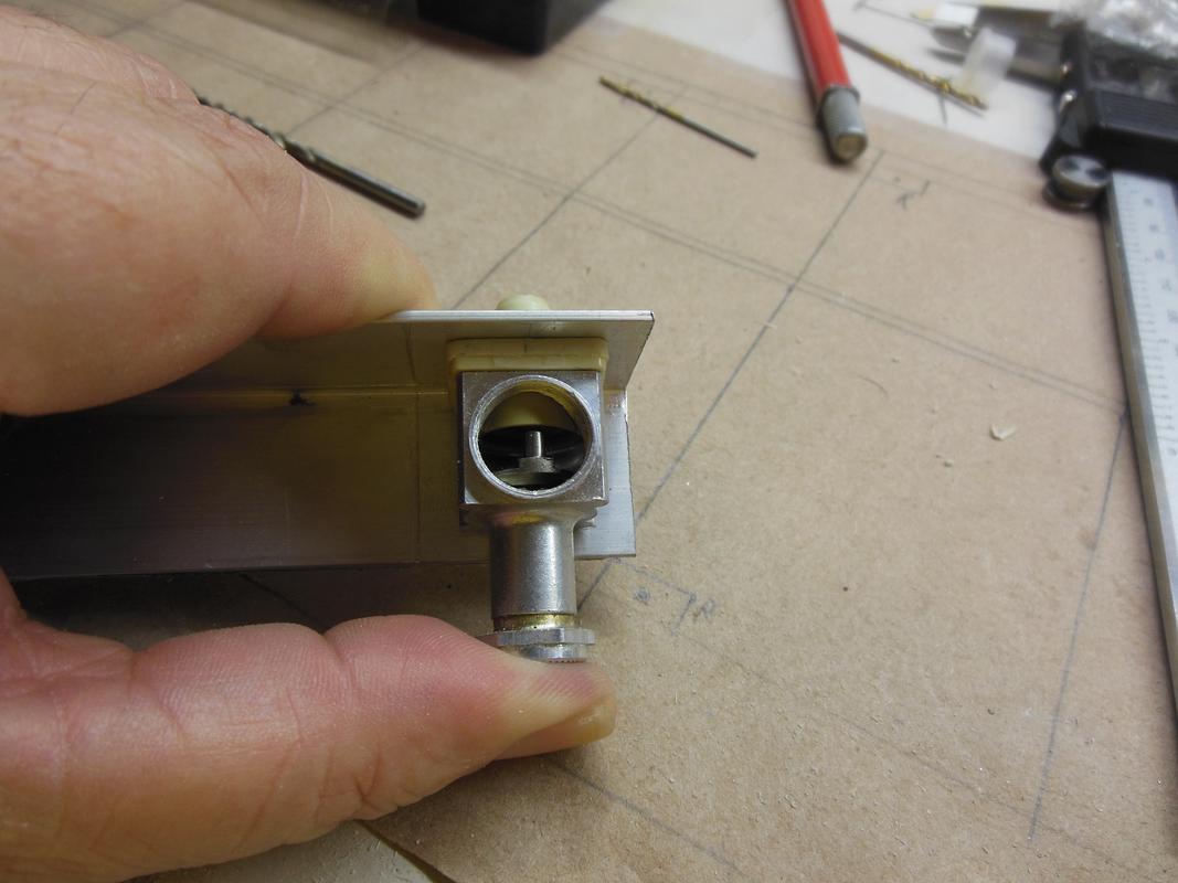
Next I did a couple of other measurements and scribed my angle stock. I determined the location of the venturi and used my auto center-punch (the second-best tool ever invented) to mark the location. A drilled pilot hole and then a quick shot with the uni-bit (THE best tool ever invented), and I had a hole for the venturi through the angle stock.

Then I scribed the lines for the backplate and drilled the mounting holes through the back of the angle. I then rough cut the mount to shape and drilled the mounting holes to match the lugs on the Medallion. I ensured that the bed was the same width as the Medallion lugs.
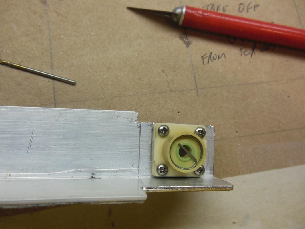

Then it was just mounting the engine to the angle mount. The standard postage stamp backplate screws work fine with the aluminum angle since I filed down the plastic on the rear of the backplate.

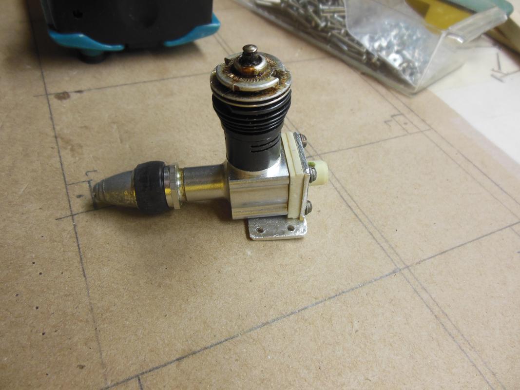
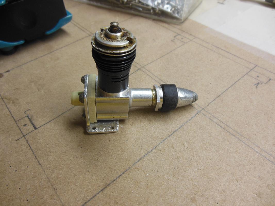
I figured that even though the beam mount from T-section was nice, it wasn’t worth it to me for the cost of materials to order online. In my workroom I have plenty of aluminum angle in 1/8” and 1/16” of various sizes. I’d image most of us guys have some in the garage or workroom. So, I thought it could be cut and shaped very quickly into a bed mount for the postage stamp backplates. I figured 1/8” is overkill, so I went with some 1/16”x1” angle.
I bought four postage stamp backplates off of eBay a couple of months ago just to get the fine needle valve assemblies. With shipping, they came out to about four bucks for each fine NVA. MUCH cheaper than the fine needle assemblies Texas Timers sells. I pulled the NVAs from the postage stamp backplates and then threw the backplates in one of my spares boxes. I dug one back out for this test.
To make this thing more useful, I decided that it had to fit the mounting holes of a Medallion or a TeeDee. The first thing I did was measure the width of a Medallion .049 case at the lugs, and then measure the width of a regular extruded reedie case. I zeroed my calipers on the Medallion case so I could see how much wider the extruded case was. The reedie case is 0.090” wider than the Medallion case. I don’t know why the image hosting site rotated the Medallion image by 90 degrees, but it won’t let me correct the rotation.
Then I trimmed off the excess plastic from the backplate and filed it smooth.
Next I did a couple of other measurements and scribed my angle stock. I determined the location of the venturi and used my auto center-punch (the second-best tool ever invented) to mark the location. A drilled pilot hole and then a quick shot with the uni-bit (THE best tool ever invented), and I had a hole for the venturi through the angle stock.
Then I scribed the lines for the backplate and drilled the mounting holes through the back of the angle. I then rough cut the mount to shape and drilled the mounting holes to match the lugs on the Medallion. I ensured that the bed was the same width as the Medallion lugs.
Then it was just mounting the engine to the angle mount. The standard postage stamp backplate screws work fine with the aluminum angle since I filed down the plastic on the rear of the backplate.
Last edited by batjac on Fri Dec 08, 2017 4:50 am; edited 2 times in total

batjac- Diamond Member


Posts : 2356
Join date : 2013-05-22
Age : 61
Location : Broken Arrow, OK, USA
Re: A Quick Aside
![]() batjac Fri Dec 08, 2017 4:35 am
batjac Fri Dec 08, 2017 4:35 am
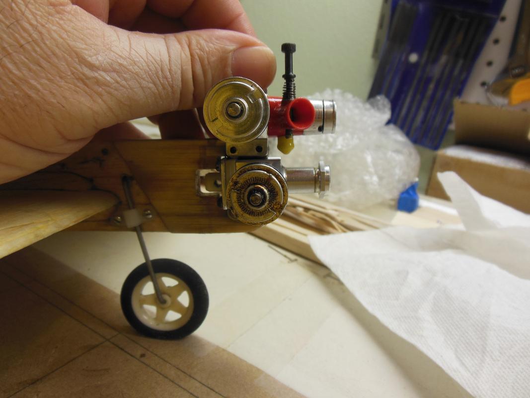
But how does it work on a plane?
I grabbed a knock-around BTC plane and mounted the Medallion on it.
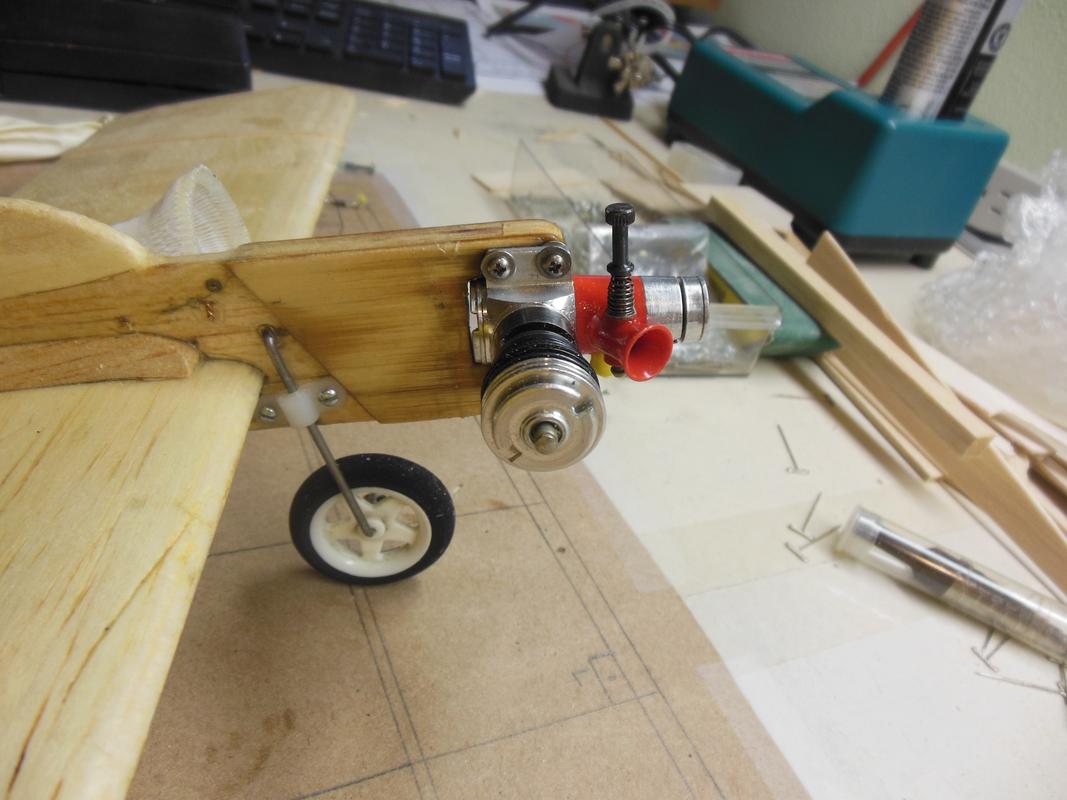

Then I mounted the reedie with the bed mount. I had to trim a little, and I cut out a notch behind the engine for the venturi sticking out. It would have been better to just trim a little on the outboard side of the fuselage instead of cutting all the way through, but I didn’t feel like digging out the Dremel tool and mounting the small sanding drum on it, so I just notched the fuse. It’s not a big enough notch to compromise the integrity of the fuselage nose, and the engine bearers actually go a long way back into the fuse on this model. Before I fly this, I’ll make up a couple of aluminum plates for the mounting screw heads to rest on so that they do not dig into the ply doubler.


With the Medallion beam mounted, the crankshaft is offset from the fuselage centerline by about 3/16”. With the reedie bed mounted, the crankshaft is almost exactly in the same position.

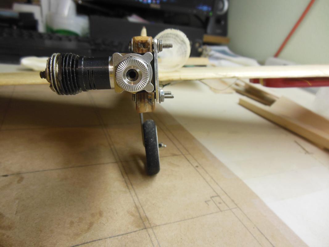
And, looking at it from the side, with the lugs on the bed mount the same dimensions as the Medallion lugs, the prop flanges of both engines are almost exactly in the same position.
So, it’s not exactly the same as a beam mount for a postage stamp backplate, but it’s close enough to get the Batjac Aeroworks seal of approval. Plus, it only used 17 cents worth of aluminum angle.
Also, with this bed mount, and a spring starter on the reedie, I figure it’ll make for an easier setup to run bladder pressure. I’ll press one of the fine NVAs back into the postage stamp backplate, and this should run great on bladder pressure with the TeeDee piston and cylinder I put on it.
The Super Secret Mark
I grabbed a knock-around BTC plane and mounted the Medallion on it.
Then I mounted the reedie with the bed mount. I had to trim a little, and I cut out a notch behind the engine for the venturi sticking out. It would have been better to just trim a little on the outboard side of the fuselage instead of cutting all the way through, but I didn’t feel like digging out the Dremel tool and mounting the small sanding drum on it, so I just notched the fuse. It’s not a big enough notch to compromise the integrity of the fuselage nose, and the engine bearers actually go a long way back into the fuse on this model. Before I fly this, I’ll make up a couple of aluminum plates for the mounting screw heads to rest on so that they do not dig into the ply doubler.
With the Medallion beam mounted, the crankshaft is offset from the fuselage centerline by about 3/16”. With the reedie bed mounted, the crankshaft is almost exactly in the same position.
And, looking at it from the side, with the lugs on the bed mount the same dimensions as the Medallion lugs, the prop flanges of both engines are almost exactly in the same position.
So, it’s not exactly the same as a beam mount for a postage stamp backplate, but it’s close enough to get the Batjac Aeroworks
seal of approval. Plus, it only used 17 cents worth of aluminum angle.Also, with this bed mount, and a spring starter on the reedie, I figure it’ll make for an easier setup to run bladder pressure. I’ll press one of the fine NVAs back into the postage stamp backplate, and this should run great on bladder pressure with the TeeDee piston and cylinder I put on it.
The Super Secret Mark
batjac- Diamond Member
-
Posts : 2356
Join date : 2013-05-22
Age : 61
Location : Broken Arrow, OK, USA
Re: A Quick Aside
![]() getback Fri Dec 08, 2017 8:55 am
getback Fri Dec 08, 2017 8:55 am
That Looks really GOOD !! And was pretty quick too , its cool that when mounted comes to very close to the Mount of the Medallion as far as alignment in the plane . Thanks for sharing that Mr. Secret ! 

getback- Top Poster

-
Posts : 10276
Join date : 2013-01-18
Age : 66
Location : julian , NC
Re: A Quick Aside
![]() roddie Fri Dec 08, 2017 9:29 am
roddie Fri Dec 08, 2017 9:29 am
Bravo Mark!  You mentioned also having some 1/8" x 1" AL angle.. but it looks like it would be too thick to clear the NVA? It's hard to tell how much clearance there is, by looking at the photos.
Not sure if you'd want to take this approach.. but if you fabricate/modify the mount having an "open-slot" on the backside/top-center and the width of the venturi; it would allow installation without removing the NVA. An open slot in that location shouldn't affect the integrity/strength of the mount.. and you would install it by simply sliding it up from the bottom, between the backplate and the NVA.
I actually have some 1/16" x 3/4" x 1.0" AL angle that would work for this.. and would save having to make the height-cut.
You mentioned also having some 1/8" x 1" AL angle.. but it looks like it would be too thick to clear the NVA? It's hard to tell how much clearance there is, by looking at the photos. Not sure if you'd want to take this approach.. but if you fabricate/modify the mount having an "open-slot" on the backside/top-center and the width of the venturi; it would allow installation without removing the NVA. An open slot in that location shouldn't affect the integrity/strength of the mount.. and you would install it by simply sliding it up from the bottom, between the backplate and the NVA.

I actually have some 1/16" x 3/4" x 1.0" AL angle that would work for this.. and would save having to make the height-cut.

roddie- Top Poster
-
Posts : 8458
Join date : 2013-07-17
Age : 64
Location : N. Smithfield, Rhode Island -

Re: A Quick Aside
![]() KariFS Fri Dec 08, 2017 12:47 pm
KariFS Fri Dec 08, 2017 12:47 pm
Again one of those "why did I not think of that?" moments 
Pretty smart!
I have some ally angle in the garage too, it may be thicker, but sanding the backplate is another possibility I had not thought of.
I see a speed plane or maybe a team racer happening, or maybe even the "Santana" by Dale Kirn
Pretty smart!
I have some ally angle in the garage too, it may be thicker, but sanding the backplate is another possibility I had not thought of.
I see a speed plane or maybe a team racer happening, or maybe even the "Santana" by Dale Kirn
KariFS- Diamond Member
- Posts : 2019
Join date : 2014-10-10
Age : 52
Re: A Quick Aside
![]() roddie Fri Dec 08, 2017 1:27 pm
roddie Fri Dec 08, 2017 1:27 pm
KariFS wrote:Again one of those "why did I not think of that?" moments
Pretty smart!
I have some ally angle in the garage too, it may be thicker, but sanding the backplate is another possibility I had not thought of.
I see a speed plane or maybe a team racer happening, or maybe even the "Santana" by Dale Kirn
I'm not familiar with that model.. but it would be cool to build one.. and "nickname" it Carlos..
roddie- Top Poster
-
Posts : 8458
Join date : 2013-07-17
Age : 64
Location : N. Smithfield, Rhode Island -
Re: A Quick Aside
![]() coxaddict Fri Dec 08, 2017 2:42 pm
coxaddict Fri Dec 08, 2017 2:42 pm
What a great idea! My Babe Beamer mounting lugs ended up wider than the TD/Medallion lugs, making it specific to custom construction of a plane. I'm thinking of using your design on a foamie saucer shaped plane, turning the mount around with the bottom  facing rearward.
 facing rearward.
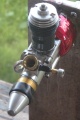
coxaddict- Gold Member

- Posts : 429
Join date : 2013-01-27
Location : north shore oahu, Hawaii
Re: A Quick Aside
![]() KariFS Fri Dec 08, 2017 3:21 pm
KariFS Fri Dec 08, 2017 3:21 pm
roddie wrote:KariFS wrote:
I see a speed plane or maybe a team racer happening, or maybe even the "Santana" by Dale Kirn
I'm not familiar with that model.. but it would be cool to build one.. and "nickname" it Carlos..
Here's the plan:
https://outerzone.co.uk/plan_details.asp?ID=7961
Pretty "Smooth" ship, no?
KariFS- Diamond Member
- Posts : 2019
Join date : 2014-10-10
Age : 52
Re: A Quick Aside
![]() batjac Fri Dec 08, 2017 3:52 pm
batjac Fri Dec 08, 2017 3:52 pm
roddie wrote:Bravo Mark!
Roddie, with the 1/8" angle, it would just barely fit. I was thinking that if I did it with 1/8' angle I would just take a half-round jeweler's file and file a shallow depression to ensure enough clearance that the needle wouldn't rub against the aluminum.
The Half-
batjac- Diamond Member
-
Posts : 2356
Join date : 2013-05-22
Age : 61
Location : Broken Arrow, OK, USA
Re: A Quick Aside
![]() batjac Fri Dec 08, 2017 3:55 pm
batjac Fri Dec 08, 2017 3:55 pm
KariFS wrote:Again one of those "why did I not think of that?" moments
Pretty smart!
I have some ally angle in the garage too, it may be thicker, but sanding the backplate is another possibility I had not thought of.
I see a speed plane or maybe a team racer happening, or maybe even the "Santana" by Dale Kirn
Kari, when I was thinking this thing up, one of the five or six versions I came up with in my head was a speed plane mount. Maybe I'll make one up this weekend and post the pictures.
The Thinker Mark
batjac- Diamond Member
-
Posts : 2356
Join date : 2013-05-22
Age : 61
Location : Broken Arrow, OK, USA
Re: A Quick Aside
![]() Oldenginerod Fri Dec 08, 2017 4:03 pm
Oldenginerod Fri Dec 08, 2017 4:03 pm
Great concept & workmanship Mark, but I'm going to play the "Devil's Advocate" for a moment.
Personally, I think you'll get some serious vibrations leading to eventual failure of the mount due to metal fatigue. I guess it will take some time and will depend on how well balanced the engine/prop set-up is, but I can imaging some pretty significant oscillations of the mount potentially happening, placing a lot of stress at the corner of the angle.
Then, I could be over-thinking, but I'd hate to see the engine suddenly part company with the plane mid-flight.

Oldenginerod- Top Poster
- Posts : 3985
Join date : 2012-06-15
Age : 61
Location : Drouin, Victoria
Re: A Quick Aside
![]() Marleysky Fri Dec 08, 2017 4:44 pm
Marleysky Fri Dec 08, 2017 4:44 pm
Oldenginerod wrote:Great concept & workmanship Mark, but I'm going to play the "Devil's Advocate" for a moment.
Then, I could be over-thinking, but I'd hate to see the engine suddenly part company with the plane mid-flight.
I don't know...I think I would want to see the the engine part company in mid flight, Just so I'd know where to start looking for it!!

Once I found it, I'd know where to beef up the mount to prevent it from happening again. I think its a slick design and adaptable for some experimentation, like on foam discs and such, just for fun.

Marleysky- Top Poster
-
Posts : 3618
Join date : 2014-09-28
Age : 71
Location : Grand Rapids, MI
Re: A Quick Aside
![]() getback Fri Dec 08, 2017 5:53 pm
getback Fri Dec 08, 2017 5:53 pm
Silly me i didn't remember that you had a back plate without a NVA That's cool Roddie seen that , You would have figured it out Mark bout the time you went to put it back together after putting the needle valve asy. back in it !?!?!? I think the structure will bee find as long as the angle bend is correct with the width of the fuse-a-loge !  The best way is A TEST !!
The best way is A TEST !!
getback- Top Poster
-
Posts : 10276
Join date : 2013-01-18
Age : 66
Location : julian , NC
Re: A Quick Aside
![]() roddie Fri Dec 08, 2017 6:43 pm
roddie Fri Dec 08, 2017 6:43 pm
Oldenginerod wrote:Great concept & workmanship Mark, but I'm going to play the "Devil's Advocate" for a moment.
Personally, I think you'll get some serious vibrations leading to eventual failure of the mount due to metal fatigue. I guess it will take some time and will depend on how well balanced the engine/prop set-up is, but I can imaging some pretty significant oscillations of the mount potentially happening, placing a lot of stress at the corner of the angle.
Then, I could be over-thinking, but I'd hate to see the engine suddenly part company with the plane mid-flight.
IMO..
 It never hurts to "over-think" a design. I sent "Eric" a set of two-piece radial-mounts that I made for the postage-stamp backplate.. and one of them failed due to fatigue. Granted; I bent my plates into shape.. whereas Mark is using extruded angle-stock.. which should be much stronger. I "do" see the concern though. If there "is" a failure.. the engine will fly-off.
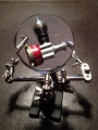
 A simple precaution can be had in a safety-cable connected under the head of a backplate-screw and the other end under the head of a beam-screw. The C/L combat-flyers are (I believe) mandated to have a safety cable to retain their engine.
Here's an example of how simple it can be to make one for this engine size.

Those are small/22AWG size ring-terminals.. and a short length of small dia. stranded-steel cable. Crimp, solder and install..
roddie- Top Poster
-
Posts : 8458
Join date : 2013-07-17
Age : 64
Location : N. Smithfield, Rhode Island -
Re: A Quick Aside
![]() batjac Fri Dec 08, 2017 10:09 pm
batjac Fri Dec 08, 2017 10:09 pm
Oldenginerod wrote:Great concept & workmanship Mark, but I'm going to play the "Devil's Advocate" for a moment.
Personally, I think you'll get some serious vibrations leading to eventual failure of the mount due to metal fatigue. I guess it will take some time and will depend on how well balanced the engine/prop set-up is, but I can imaging some pretty significant oscillations of the mount potentially happening, placing a lot of stress at the corner of the angle.
Then, I could be over-thinking, but I'd hate to see the engine suddenly part company with the plane mid-flight.
Rod, I did think about that. I made sure that there were no sharp angles when cutting the mount. I didn't file the corners of the mount. I drilled holes at the corners and then cut to them. I filed the flats and did the final shaping at the corners with a round jeweler's file to ensure there were no stress risers. After that, just inspecting before flight for any cracks should be good. With all the fuel being spit out from the engine, a crack will be pretty easy to see.
Roddie, I did think about a tether also. But I'll just stick with pre-flight inspections. As you probably know about me by now, I only fly my planes a few times before I hang them up and start on another plane. In fact, I have more planes waiting for their first flight than I know what to do with...
The Plane Poor Mark
batjac- Diamond Member
-
Posts : 2356
Join date : 2013-05-22
Age : 61
Location : Broken Arrow, OK, USA
Re: A Quick Aside
![]() KariFS Sat Dec 09, 2017 4:27 am
KariFS Sat Dec 09, 2017 4:27 am
I agree with Rod that oscillations may occur, but on the other hand, as mentioned, extruded angle is much stiffer than what bent sheet would be. Resistance to fatigue is also better, since the profile was "born" in that shape, hence it does not contain any stress damage that a bent profile inherently has.
There is always the possibility to use thicker-walled profile. I am sure that 1/8" would be enough to keep things solid, no matter how out of balance things might be, even with some additional slots and such to allow the installation of the nva.
A thicker profile might even work as a support point for the landing gear
KariFS- Diamond Member
- Posts : 2019
Join date : 2014-10-10
Age : 52
Re: A Quick Aside
![]() batjac Sat Dec 09, 2017 11:39 pm
batjac Sat Dec 09, 2017 11:39 pm
KariFS wrote:A thicker profile might even work as a support point for the landing gear
Or it might be the landing gear? I figured for a speed plane, I might as well just make the landing gear integral with the engine mount. It actually takes less effort to extend one lug as the landing gear than it does to shape that lug to match the Medallion profile.
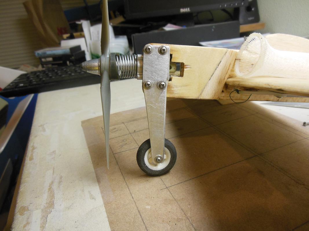
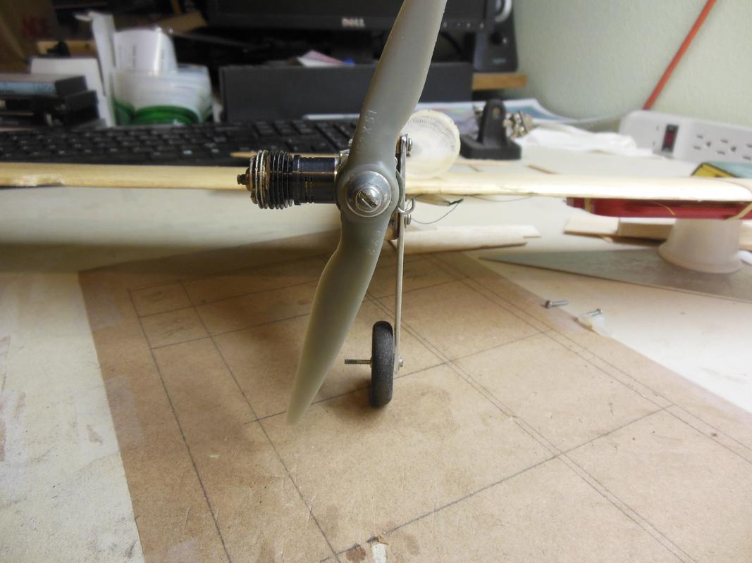
The Efficient Mark
batjac- Diamond Member
-
Posts : 2356
Join date : 2013-05-22
Age : 61
Location : Broken Arrow, OK, USA
Re: A Quick Aside
![]() Ken Cook Sun Dec 10, 2017 6:48 am
Ken Cook Sun Dec 10, 2017 6:48 am
Mark, your gear will also serve a double purpose like that because it's now a heat sink as well.
Ken Cook- Top Poster
- Posts : 5542
Join date : 2012-03-27
Location : pennsylvania
» sorry nieghbors but i needed a quick fix
» Well, that was quick. Two Wen Mac .049's arrive
» Kyosho .049 Cox VW Beetle / Mini Cooper
» Quick or slow set epoxy
» Quick Cox Glowhead Question
» Well, that was quick. Two Wen Mac .049's arrive
» Kyosho .049 Cox VW Beetle / Mini Cooper
» Quick or slow set epoxy
» Quick Cox Glowhead Question
Page 1 of 1
Permissions in this forum:
You cannot reply to topics in this forum