

 Rules
Rules
Log in
Search
Latest topics
» Looking For Comet Tri-Pacerby DanMc Today at 7:25 pm
» "Red Neck" .049 elec. starter
by 944_Jim Today at 7:04 pm
» Cox AT-6 Texan repaint.....Pretty nice
by 944_Jim Today at 4:31 pm
» Prayers for my Wife Please
by balogh Today at 4:08 pm
» Jim Walkers FireBee - This is going to be fun
by rdw777 Today at 3:58 pm
» Hawk had breakfast and then took a bath
by rdw777 Today at 3:46 pm
» Roddie's water-cooling bottle for bench-running
by roddie Today at 3:07 pm
» Removing old decals
by latole Today at 3:06 pm
» Prop Rod - resto to a runner
by rsv1cox Today at 2:29 pm
» Cox Ryan ST 2.0
by 944_Jim Today at 11:52 am
» Blue backplate postage stamp engine
by getback Today at 6:46 am
» COX Postage Stamp engine -Babe Bee & Horseshoe Backplate adapters
by GallopingGhostler Today at 6:33 am


CEF Traveling Engine

Win This Engine!
Live on Patrol


Shimming Cox Cylinder for Transfer and Exhaust Timing
Page 1 of 1

Shimming Cox Cylinder for Transfer and Exhaust Timing
![]() sosam117 Tue Apr 14, 2020 9:47 pm
sosam117 Tue Apr 14, 2020 9:47 pm
Shimming Cox Engines --- Port / Timing Guide
by M. McIntyre
Because of an accumulation of tolerances of production tolerances, the crown of the piston can, and often does, extend above the inside shoulder of the cylinder when the piston is at top dead center (ATDC). Optimum, design, transfer and exhaust porting occurs when the crown of the piston is exactly level with the shoulder ATDC. One way to check this is with a depth micrometer. However, since most modelers do not have such micrometers, here is another way.
Take a piece of thin (.010” or 0.25mm) brass shim stock, and cut a full moon circle (disc), that will fit into the top of the cylinder head – the approximation diameter of a copper glow head gasket. Cut (drill or punch), an air bleed hole in the center of the disc, and be sure there are no burrs anywhere on the disc. Now, take an old, burnt out glow head, and remove the center stem (glow wire, etc.). The objective is to convert it into a screw-in hold-down insert that will not be pressure tight. Or you can purchase a glow head adapter to do the same? See fig. #1
With the engine assembled, place the bass disc on the cylinder shoulder, and screw in the insert (or glow head adapter). See fig. #2 – alias glow head. Thus, when you gently rotate the crankshaft, you’ll feel the piston “bump” and stop against the disc, if it were to try to pass the shoulder ATDC. See fig. #3 Now, loosen the cylinder from the crankcase until you cannot feel a “bump” or obstruction ATDC. With a set of feller gages insert a shim between the bottom of the cylinder and crankcase (at the threads location). This will give you an idea of the proper shim required.
I purchased a punch and die set to make my own shims. Also purchased was a step less reamer. See fig. #4 and #5. You will also need brass shim stock or aluminum shim stock (.002” / .003” / .005”). The first hole in the shim stock will be ½” diameter (see fig. #6), but the hole is not big enough to slip over threads on the cylinder (after the threads it is). That is where the step less reamer is used to enlarge the hole, (See fig. #7) just large enough to slip past the threads on the cylinder. See fig. #8 and #9.
Next, insert the shim stock to the ¾” hole on the punch, and try to center it the best you can to the ½” hole on the shim stock. See fig. #10 Now punch out you shim at the ¾” hole with the die See fig. #11 and fig. #12
Slip your shim onto the bottom of the cylinder, then screw the cylinder to the crankcase. Your shim should be between the cylinder and the crankcase. The cylinder should have been raised enough to just clear the brass disc which is still screwed into the top of the cylinder head (on the shoulder – See fig. #13 and #3) with no “bump” feeling. Then you’ll know that the proper shimming has been ascertained.
Next step, using an Exacto knife, score the brass shim (or aluminum shim) around the cylinder while it is still screwed to the crankcase. See fig. #14 Remove the cylinder and shim from the crankcase. Remove the shim from the bottom of the cylinder. You should be able to see a scored circle on your brass shim (or aluminum shim). See fig. #15 Using a good heavy pair of sharp scissors start cutting the shim stock to the scored circle on the brass shim. See fig. #16 Cut off all the extra shim stock to the scored circle until none is left. See fig. #17 I use a very file sanding block (nail file) with 220 grit sand paper to sand the shim to a more rounded shape. The width of the shim will be about 1/32 wide.
Install the shim back onto the cylinder, then the cylinder back on to the crankcase, making sure when the cylinder contacts the crankcase the shim is centered under the cylinder. See fig. #18 and #19 and tighten the cylinder to the crankcase. Check ATDC one more time for correct shim height. After that is done, remove the (glow) head insert and brass disc, and install a copper head gasket and functional glow head.
Your engine now has the correct designed transfer and exhaust timing. Note, however that the optimum performance my vary from this position. In particular, be sure that you still have about .012” (0.30mm) sub-piston induction (SPI) when the piston is ATDC.
Years ago, Kustom Kraftsmanship (owner: Joe Klause) sold shim kits, stock #181 which had four different shim sizes and a shim housing. The shim housing fits neatly over the crankcase shoulder and the shims slipped into the shim housing (so the shims were not bent when the cylinder was screwed on). Kustom Kraftsmanship is no longer in business --- it’s a shame. You could get good custom parts for any Cox engines.
If you purchase your own punch and die set, here is a tip before you start using it. First, clean any oil or rust preventative off the punches and die. Next, turn over your die (steel plate with holes in it), so the plexiglass is on the bottom. Grab one of your punches and insert it through the metal side of the die (as if you are going to punch a hole.) Now knock it all the way through. What this does is to shave the plexiglass so it will be exactly lined up to the metal plate below. If you don’t do this, the first time you use it, it will either crack the plexiglass, or damage the cutting edge on the punch. Do this until the punch fall through, then move onto the next punch hole until all are done. When you do use your punch and die set make sure that you punches do not drop onto the floor or any hard surface to where it damages the cutting edge of the punch (nick or burr).
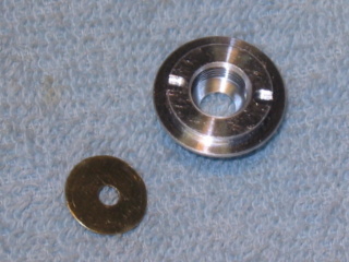
Fig. #1
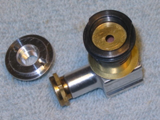
Fig. #2
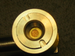
Fig. #3
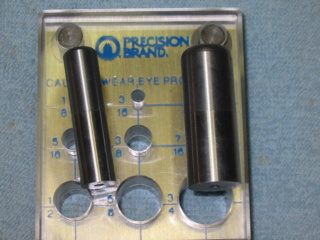
Fig. #4
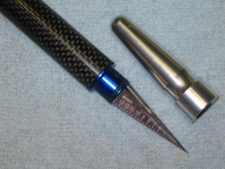
Fig. #5

Fig. #6

Fig. #7
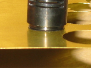
Fig. #8
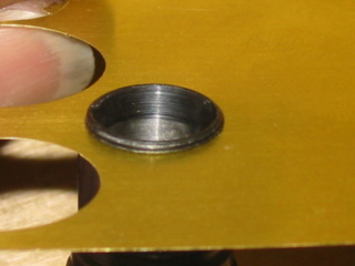
Fig. #9

Fig. #10
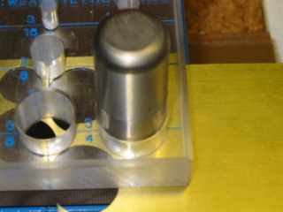
Fig. #11
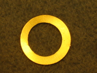
Fig. #12
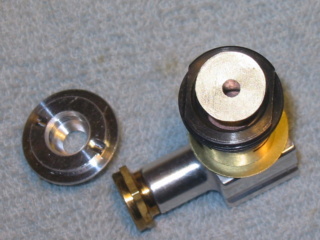
Fig. #13
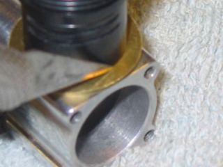
Fig. #14
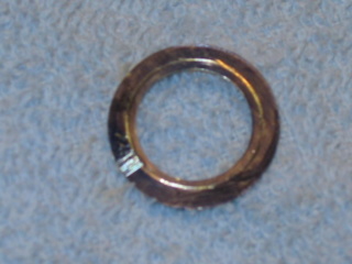
Fig. #15
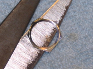
Fig. #16

Fig. #17
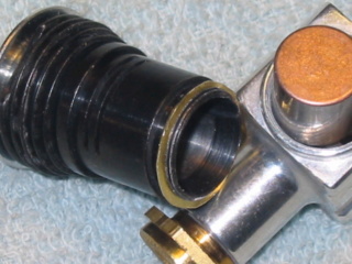
Fig. #18
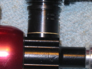
Fig. #19
by M. McIntyre
Because of an accumulation of tolerances of production tolerances, the crown of the piston can, and often does, extend above the inside shoulder of the cylinder when the piston is at top dead center (ATDC). Optimum, design, transfer and exhaust porting occurs when the crown of the piston is exactly level with the shoulder ATDC. One way to check this is with a depth micrometer. However, since most modelers do not have such micrometers, here is another way.
Take a piece of thin (.010” or 0.25mm) brass shim stock, and cut a full moon circle (disc), that will fit into the top of the cylinder head – the approximation diameter of a copper glow head gasket. Cut (drill or punch), an air bleed hole in the center of the disc, and be sure there are no burrs anywhere on the disc. Now, take an old, burnt out glow head, and remove the center stem (glow wire, etc.). The objective is to convert it into a screw-in hold-down insert that will not be pressure tight. Or you can purchase a glow head adapter to do the same? See fig. #1
With the engine assembled, place the bass disc on the cylinder shoulder, and screw in the insert (or glow head adapter). See fig. #2 – alias glow head. Thus, when you gently rotate the crankshaft, you’ll feel the piston “bump” and stop against the disc, if it were to try to pass the shoulder ATDC. See fig. #3 Now, loosen the cylinder from the crankcase until you cannot feel a “bump” or obstruction ATDC. With a set of feller gages insert a shim between the bottom of the cylinder and crankcase (at the threads location). This will give you an idea of the proper shim required.
I purchased a punch and die set to make my own shims. Also purchased was a step less reamer. See fig. #4 and #5. You will also need brass shim stock or aluminum shim stock (.002” / .003” / .005”). The first hole in the shim stock will be ½” diameter (see fig. #6), but the hole is not big enough to slip over threads on the cylinder (after the threads it is). That is where the step less reamer is used to enlarge the hole, (See fig. #7) just large enough to slip past the threads on the cylinder. See fig. #8 and #9.
Next, insert the shim stock to the ¾” hole on the punch, and try to center it the best you can to the ½” hole on the shim stock. See fig. #10 Now punch out you shim at the ¾” hole with the die See fig. #11 and fig. #12
Slip your shim onto the bottom of the cylinder, then screw the cylinder to the crankcase. Your shim should be between the cylinder and the crankcase. The cylinder should have been raised enough to just clear the brass disc which is still screwed into the top of the cylinder head (on the shoulder – See fig. #13 and #3) with no “bump” feeling. Then you’ll know that the proper shimming has been ascertained.
Next step, using an Exacto knife, score the brass shim (or aluminum shim) around the cylinder while it is still screwed to the crankcase. See fig. #14 Remove the cylinder and shim from the crankcase. Remove the shim from the bottom of the cylinder. You should be able to see a scored circle on your brass shim (or aluminum shim). See fig. #15 Using a good heavy pair of sharp scissors start cutting the shim stock to the scored circle on the brass shim. See fig. #16 Cut off all the extra shim stock to the scored circle until none is left. See fig. #17 I use a very file sanding block (nail file) with 220 grit sand paper to sand the shim to a more rounded shape. The width of the shim will be about 1/32 wide.
Install the shim back onto the cylinder, then the cylinder back on to the crankcase, making sure when the cylinder contacts the crankcase the shim is centered under the cylinder. See fig. #18 and #19 and tighten the cylinder to the crankcase. Check ATDC one more time for correct shim height. After that is done, remove the (glow) head insert and brass disc, and install a copper head gasket and functional glow head.
Your engine now has the correct designed transfer and exhaust timing. Note, however that the optimum performance my vary from this position. In particular, be sure that you still have about .012” (0.30mm) sub-piston induction (SPI) when the piston is ATDC.
Years ago, Kustom Kraftsmanship (owner: Joe Klause) sold shim kits, stock #181 which had four different shim sizes and a shim housing. The shim housing fits neatly over the crankcase shoulder and the shims slipped into the shim housing (so the shims were not bent when the cylinder was screwed on). Kustom Kraftsmanship is no longer in business --- it’s a shame. You could get good custom parts for any Cox engines.
If you purchase your own punch and die set, here is a tip before you start using it. First, clean any oil or rust preventative off the punches and die. Next, turn over your die (steel plate with holes in it), so the plexiglass is on the bottom. Grab one of your punches and insert it through the metal side of the die (as if you are going to punch a hole.) Now knock it all the way through. What this does is to shave the plexiglass so it will be exactly lined up to the metal plate below. If you don’t do this, the first time you use it, it will either crack the plexiglass, or damage the cutting edge on the punch. Do this until the punch fall through, then move onto the next punch hole until all are done. When you do use your punch and die set make sure that you punches do not drop onto the floor or any hard surface to where it damages the cutting edge of the punch (nick or burr).
Fig. #1
Fig. #2
Fig. #3
Fig. #4
Fig. #5
Fig. #6
Fig. #7
Fig. #8
Fig. #9
Fig. #10
Fig. #11
Fig. #12
Fig. #13
Fig. #14
Fig. #15
Fig. #16
Fig. #17
Fig. #18
Fig. #19
Last edited by sosam117 on Mon Jul 06, 2020 2:49 pm; edited 2 times in total (Reason for editing : grammar and misspellings)
sosam117- Diamond Member

- Posts : 1293
Join date : 2016-03-23
Location : Suburb of Chicago, Illinois
Re: Shimming Cox Cylinder for Transfer and Exhaust Timing
![]() davidll1984 Tue Apr 14, 2020 11:19 pm
davidll1984 Tue Apr 14, 2020 11:19 pm
its texaco tank reed its smaler ventury wat is rpm after mod ? on my wit fuel tank from pinto tether drag cars it as biger ventury and extra part in back plate my wit smal tank run 22k to 23 000 without shimming cylinder or glow head no hy comp head just standar one prop is 6x3 winsor

davidll1984- Diamond Member
- Posts : 2293
Join date : 2020-02-12
Age : 39
Location : shawinigan
Re: Shimming Cox Cylinder for Transfer and Exhaust Timing
![]() Basswood Wed Apr 15, 2020 3:50 am
Basswood Wed Apr 15, 2020 3:50 am
A lot of great info here thanks sosam117. I'm playing the same game with mine. compression/stroke/SPI.
Basswood
Basswood
Basswood- Gold Member

- Posts : 141
Join date : 2020-02-19
Age : 67
Location : Phoenix, Az.
Re: Shimming Cox Cylinder for Transfer and Exhaust Timing
![]() Oldenginerod Wed Apr 15, 2020 5:46 am
Oldenginerod Wed Apr 15, 2020 5:46 am
There is one part of the procedure that may sound a little confusing, and misleading. The statement "Screw the shim onto the cylinder head, then screw the cylinder head to the crankcase" gives the impression that the shim is between the head and the cylinder, when in fact the shim is between the cylinder and the crankcase.
The method described should also give optimal compression with just one head gasket. The shim would also alter the position of the exhaust ports. I'm not sure which is preferred, having the ports evenly spaced to either side of the engine, or having the ports fore and aft so that the airflow can help scavenge exhaust fumes from the cylinder.
Because of machining variances, having the correct "bump clearance" won't necessarily give exactly the optimal port timing and SPI clearance. There are a number of variables that need to be considered. It may be necessary to have the cylinder lower to adjust the correct SPI and compensate by installing extra head shims to stop the "bump" on the head.

Oldenginerod- Top Poster

- Posts : 3975
Join date : 2012-06-15
Age : 61
Location : Drouin, Victoria
» Shimming Cox Cylinder for Transfer and Exhaust Timing
» New Uploads: KK Shimming / Timing guide and Cox Parts Price Lists from 1995 and 1996
» Cylinder Performance Figures
» Cylinder shimming
» Cylinder Timing
» New Uploads: KK Shimming / Timing guide and Cox Parts Price Lists from 1995 and 1996
» Cylinder Performance Figures
» Cylinder shimming
» Cylinder Timing
Page 1 of 1
Permissions in this forum:
You cannot reply to topics in this forum