

 Rules
Rules
Log in
Search
Latest topics
» A choke-tube with velocity-stack configured Beeby roddie Today at 10:48 am
» Hawk had breakfast and then took a bath
by rsv1cox Today at 10:26 am
» Jim Walkers FireBee - This is going to be fun
by getback Today at 9:55 am
» WenMac 049 - Glow Plug & Head Gasket replacements?
by Ken Cook Today at 8:06 am
» Prop Rod - resto to a runner
by rsv1cox Today at 7:32 am
» Jim Walker Firebaby
by rdw777 Yesterday at 4:58 pm
» Nostalgia alert, my 1959 Corvette revisited
by rsv1cox Yesterday at 2:25 pm
» Prayers for my Wife Please
by akjgardner Yesterday at 10:28 am
» Cox prop rod
by Wiggy Fri May 17, 2024 4:30 pm
» "Red Neck" .049 elec. starter
by getback Fri May 17, 2024 7:19 am
» Cox prop rod
by Wiggy Fri May 17, 2024 5:35 am
» Looking For Comet Tri-Pacer
by latole Fri May 17, 2024 3:45 am


CEF Traveling Engine


Win This Engine!

Live on Patrol


1/8" balsa I-beam wing spars
Page 1 of 1

1/8" balsa I-beam wing spars
![]() roddie Sun Sep 15, 2013 4:03 pm
roddie Sun Sep 15, 2013 4:03 pm
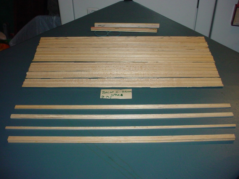
I made these on a CNC router, but it can be done carefully using a std. router/table w/fence and a simple jig you can make.
It's a 3-pc. spar, assembled w/thin CA. You will need (x2 pcs.) 1/8" x 1/2" balsa strips and (x1) 1/8" x 1/4" balsa strip; the desired length of the spar (not necessarily the span of the wing).
Make a jig of the same length as the balsa stock you're using; with a lip on the end, that will engage the stock, and "pull it through" at the back-end while routing. (use the router/table to make the jig... i.e. rout an open joint; 1/8" deep x 1/2" w. on the edge of the jig; the length of your balsa stock.) This jig serves 4 functions; it will hold your work-piece "flat" (for a consistent "depth" joint) hold your pc. against the "fence" while running it through (for a consistent "width" joint) the "lip" acts as a "push-stick"... and finally; the jig protects your fingers while routing these sm. pieces.
Once you've made the jig; Set up your router with a 1/8" straight cutter; set to 1/16" depth, and set the fence for a 1/4" offset; on the cutter's center. Place one of the 1/2"w. balsa strips in the jig, and feed it through the router; keeping the jig tight against the fence. Do the same, for the other 1/2"w. pc.
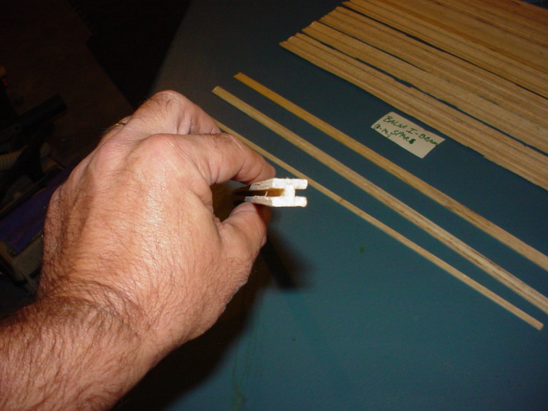
You now have the top and bottom of your I-beam, with 1/16" deep x 1/8"w. "channels"... running down the center; into which you will insert the 3rd 1/4"w. balsa strip. If your balsa is 1/8" strong on thickness; you may have to lightly "block-sand" the 1/4"w. pc. to fit into the channels. A snug fit is desirable... because you want the thin CA glue to "wick" into the joint, for optimal strength. Be sure to assemble/glue-up on a level surface.
This makes a VERY STRONG and VERY LIGHTWEIGHT wing spar, that measures; 1/2"w. x 3/8" thick, x your design length. Give it a try on your next built-up wing.

It's a 3-pc. spar, assembled w/thin CA. You will need (x2 pcs.) 1/8" x 1/2" balsa strips and (x1) 1/8" x 1/4" balsa strip; the desired length of the spar (not necessarily the span of the wing).
Make a jig of the same length as the balsa stock you're using; with a lip on the end, that will engage the stock, and "pull it through" at the back-end while routing. (use the router/table to make the jig... i.e. rout an open joint; 1/8" deep x 1/2" w. on the edge of the jig; the length of your balsa stock.) This jig serves 4 functions; it will hold your work-piece "flat" (for a consistent "depth" joint) hold your pc. against the "fence" while running it through (for a consistent "width" joint) the "lip" acts as a "push-stick"... and finally; the jig protects your fingers while routing these sm. pieces.
Once you've made the jig; Set up your router with a 1/8" straight cutter; set to 1/16" depth, and set the fence for a 1/4" offset; on the cutter's center. Place one of the 1/2"w. balsa strips in the jig, and feed it through the router; keeping the jig tight against the fence. Do the same, for the other 1/2"w. pc.
You now have the top and bottom of your I-beam, with 1/16" deep x 1/8"w. "channels"... running down the center; into which you will insert the 3rd 1/4"w. balsa strip. If your balsa is 1/8" strong on thickness; you may have to lightly "block-sand" the 1/4"w. pc. to fit into the channels. A snug fit is desirable... because you want the thin CA glue to "wick" into the joint, for optimal strength. Be sure to assemble/glue-up on a level surface.
This makes a VERY STRONG and VERY LIGHTWEIGHT wing spar, that measures; 1/2"w. x 3/8" thick, x your design length. Give it a try on your next built-up wing.

roddie- Top Poster

- Posts : 8325
Join date : 2013-07-17
Age : 64
Location : N. Smithfield, Rhode Island -

Re: 1/8" balsa I-beam wing spars
![]() roddie Sun Sep 15, 2013 8:22 pm
roddie Sun Sep 15, 2013 8:22 pm
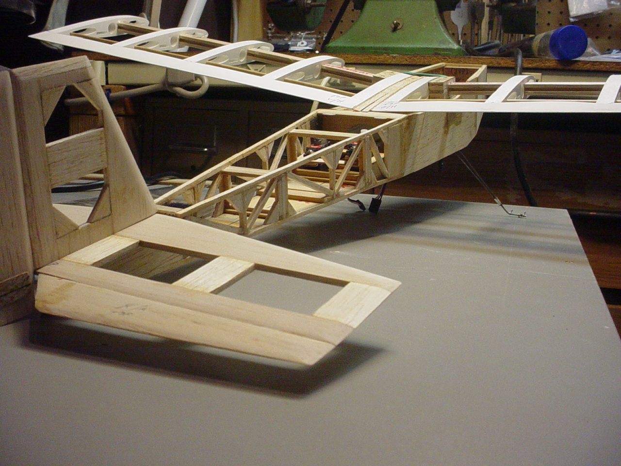
Here's an example of this I-beam spar design, used in a wing panel I'm building for an RC application.
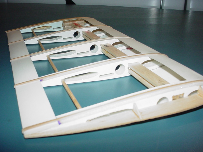
Here's a lay-up of the plane so far.

 " />
" />
Here's a lay-up of the plane so far.
" />
roddie- Top Poster
- Posts : 8325
Join date : 2013-07-17
Age : 64
Location : N. Smithfield, Rhode Island -
Re: 1/8" balsa I-beam wing spars
![]() pkrankow Sun Sep 15, 2013 9:36 pm
pkrankow Sun Sep 15, 2013 9:36 pm
The model you are building is is a worthy design use.
My initial thoughts were the stressed-skin designs where the spar is built into the wing so the spars are on the surface with a shear web joining the spars. The I-beam spar would add weight or remove strength on many plans I have consulted recently.
There are quite a few different designs out there. Consulting the plan and engineering the best possible spar for strength-to-weigh would need evaluation.
Now that I see the application, I like the idea.
Phil

pkrankow- Top Poster
- Posts : 3025
Join date : 2012-10-02
Location : Ohio
Re: 1/8" balsa I-beam wing spars
![]() roddie Mon Sep 16, 2013 11:35 am
roddie Mon Sep 16, 2013 11:35 am
Thanks for your input Phil. Those spar components pictured; I had the "luxury" of cutting on a CNC router where I used to work. I used "B"-grain 3"w. 1/8" sheets x 36"L.
Using a 1/8" dia. endmill; I set the depth to leave approx. .003" "web" of balsa to hold the pcs. together, and keep them from moving on the vacuum table. This left "flash" that could be lightly sanded-off later. Yield was 2, 2-1/2 "spar-sets" per sheet.
When I glued the 1st spar together, I was curious as to "how strong" it actually was. I won't tell you that I "couldn't" break it... but it was VERY strong; mostly because of it being a "dado" joint. Having "3" glue-bearing surfaces; both "top and bottom" gives the thin CA a lot of area to "wick" into, and "locks" the components together. Butt-joints wouldn't be nearly as strong.
The 22" long assembled spar in the pic weighs 0.20 oz. (6 gr.)
roddie- Top Poster
- Posts : 8325
Join date : 2013-07-17
Age : 64
Location : N. Smithfield, Rhode Island -
Re: 1/8" balsa I-beam wing spars
![]() OVERLORD Mon Sep 16, 2013 2:23 pm
OVERLORD Mon Sep 16, 2013 2:23 pm
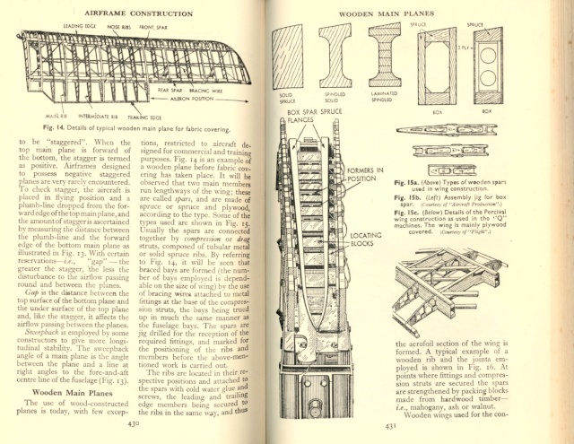
Very nice, Roger. I admire the fact to innovate modelling and conceiving new ways of constructing things. Your work looks very professional. I spars were used in 1:1 scale wooden wings as well.
What about torsional strength? Wouldn't it give a better support if the rib openings were also H shaped?
Lieven
What about torsional strength? Wouldn't it give a better support if the rib openings were also H shaped?
Lieven

OVERLORD- Diamond Member

- Posts : 1791
Join date : 2013-03-19
Age : 57
Location : Normandy, France
Re: 1/8" balsa I-beam wing spars
![]() roddie Mon Sep 16, 2013 8:34 pm
roddie Mon Sep 16, 2013 8:34 pm
Thank You Lieven, I'm not sure how "professional" my work is... from an aeronautical standpoint... but to answer your question; I designed my own ribs for this spar, which were also CNC routered. They have a spar-pocket that measures 1/2" x 3/8"... (the size of the spar... I also had to "relieve" the inside corners about 1/16"... can't fit a square peg in a round hole...)OVERLORD wrote:Very nice, Roger. I admire the fact to innovate modelling and conceiving new ways of constructing things. Your work looks very professional. I spars were used in 1:1 scale wooden wings as well.
What about torsional strength? Wouldn't it give a better support if the rib openings were also H shaped?
Lieven
The ribs are made of 1/2" "Ultra-board" which is a polystyrene foam-core; faced ea. side w/.015" polystyrene sheet. Routing involves "masking" one side of the sheet w/.003" sticky-paper and placing "paper-side" down on the machine's vacuum table, and cutting through the foam-board plus approx. .0015" into the paper... but not "through it". The sticky-paper holds all your pcs. together... and you simply "peel them off" after, when your ready to use them. I've made lots of different parts for my models in this way.
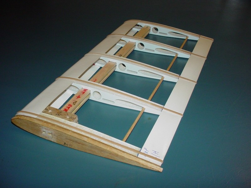
Here's a pic of a CNC router-cut wing rib...

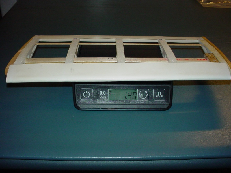
and the weight of a wing rib...

and the weight of a 14" wing-panel (less the Tower-Kote covering and gluing up the leading edge and cap strips)
Leading/trailing edges and rib cap-strips are .012" poster board construction. Without the cap-strips; I will have trouble with the foam melting when covering... even with low heat Tower-Kote covering material.
roddie- Top Poster
- Posts : 8325
Join date : 2013-07-17
Age : 64
Location : N. Smithfield, Rhode Island -
Re: 1/8" balsa I-beam wing spars
![]() pkrankow Mon Sep 16, 2013 9:43 pm
pkrankow Mon Sep 16, 2013 9:43 pm
Here I thought you had some very white wood...
I hope it flies as good as it looks.
I hope it flies as good as it looks.
pkrankow- Top Poster
- Posts : 3025
Join date : 2012-10-02
Location : Ohio
Re: 1/8" balsa I-beam wing spars
![]() roddie Mon Sep 16, 2013 11:06 pm
roddie Mon Sep 16, 2013 11:06 pm
Well Phil... I may have "screwed myself" with this airfoil. I cut the ribs "years" ago... and wanted to use them for something... along with the 3-pc. I-beam spars that were made for them. It has a 90+% symmetrical airfoil. The plane I'm building is a self-designed "high-wing" RC trainer with 3ch. (throttle/elev./rudder) controls. It should have a "lifting" airfoil... and it doesn't. I'm not sure at this point; how much dihedral to build in. Possibly as much as 6 deg./wing panel. At any rate... it's going to fly (if... it flies...) too fast with that airfoil; for a trainer. Maybe a higher wing incidence angle will help me. Time will tell.pkrankow wrote:Here I thought you had some very white wood...
I hope it flies as good as it looks.
roddie- Top Poster
- Posts : 8325
Join date : 2013-07-17
Age : 64
Location : N. Smithfield, Rhode Island -
Re: 1/8" balsa I-beam wing spars
![]() pkrankow Tue Sep 17, 2013 6:51 am
pkrankow Tue Sep 17, 2013 6:51 am
Put flaps on it for better low speed.
The wing is more suited to stunt with this airfoil, so make sure it stays with the plane.
You can change the angle of the wing to affect flight character.
Phil
The wing is more suited to stunt with this airfoil, so make sure it stays with the plane.
You can change the angle of the wing to affect flight character.
Phil
pkrankow- Top Poster
- Posts : 3025
Join date : 2012-10-02
Location : Ohio
Re: 1/8" balsa I-beam wing spars
![]() roddie Tue Sep 17, 2013 12:21 pm
roddie Tue Sep 17, 2013 12:21 pm
I wish I'd had access to multiple airfoil plots; when I made those foam ribs. Fact is... I didn't have any...
I ran CNC table routers for a sign company. We used CAD graphics "plot" files of various shapes, customer logo's, and lettering in different style "fonts" to cut dimensional pieces on the machines. You could "re-size" anything you wanted... but you couldn't create/draw your own shape with the software I had access to.
My rib's airfoil-profile is a result of choosing a (nearly symmetrical) exclamation point's "top half" and re-sizing it to my needs... but only "symmetrically". It's all I had to work with at the time. Had I had access to files containing French-curve "arc-segments"... I could have made 2nd cuts on the bottom, to alter the camber... to any airfoil-profile I wanted.
I'd love to have access to those machines again... I have a lot of model parts that I made, using them; Wheels-(various sizes), .080" alum. bell-cranks (a resized letter "T") bell-crank "bearings" made of Lexan, flywheels, motor-mounts, profile fuse's, Lexan control horns... just to name a few.
roddie- Top Poster
- Posts : 8325
Join date : 2013-07-17
Age : 64
Location : N. Smithfield, Rhode Island -
» balsa slab-wing 1/2A U-Control
» Narrowing engine bearers
» "Molding Balsa"...NOT to be confused with "Moldy Balsa"!!!!! M.A.N 12-64
» Beam mounts
» TD/Medallion beam mount
» Narrowing engine bearers
» "Molding Balsa"...NOT to be confused with "Moldy Balsa"!!!!! M.A.N 12-64
» Beam mounts
» TD/Medallion beam mount
Page 1 of 1
Permissions in this forum:
You cannot reply to topics in this forum