

 Rules
Rules
by getback Today at 7:24 am
» Foam hand kids glider converted to 0.049 CL
by getback Today at 7:23 am
» Roddie-Rigger.. a 2005 original design
by getback Today at 7:17 am
» Golden Bee basic running problem
by roddie Yesterday at 11:51 pm
» Simple Gliders
by rdw777 Yesterday at 7:25 pm
» Weird search for a single comic from an old Mad Magazine
by Kim Yesterday at 2:44 pm
» Scientific "Zipper" Build...Zipper Flys!.
by getback Yesterday at 8:27 am
» Cox .049 Tee Dee engines back in stock (limited availablility)
by GallopingGhostler Yesterday at 2:05 am
» Very off-topic.........Time passes and not always for the best......
by rsv1cox Thu Jul 25, 2024 3:47 pm
» Jim Walker Bonanza etc.
by rsv1cox Wed Jul 24, 2024 7:30 pm
» Throttles for Cox Tee Dee .049 / .020 / .010 engines --- videos
by sosam117 Wed Jul 24, 2024 9:54 am
» Introducing our Cox .049 TD Engines
by Admin Tue Jul 23, 2024 3:00 am
robot797's
"ULTIMITE COX 010: it has a clutch, E starter, throttle, exhaust, aluminum tank, aluminum venturi, gearbox with forward and reverse, and now its on a custom drawn and printed stand"

PAST WINNERS


Roddie-Rigger.. a 2005 original design
Page 1 of 2 • 1, 2 ![]()

Roddie-Rigger.. a 2005 original design
![]() roddie Thu Apr 25, 2024 4:39 pm
roddie Thu Apr 25, 2024 4:39 pm
Here's a CAD image of all the parts that make up the rigger-design from back then. I could "pull" parts from this file.. and cut them from the various materials listed.

I made a boxful of parts that had been in storage since then.. and I had also mocked-up a hull that's been kicking-around.. well.. for way too long.. and has workshop-rash to prove it.
Shown below; with prospective Cox .049 reed-valve engine and 2mm shaft (wire) drive. This would come together quickly at this point/stage in time.

Since I've been sourcing parts for the Cox powered jet-pump.. it's rekindled my interest. I un-buried the rigger's box-o-parts and thought; "what a shame to let this keep sitting.."

Apparently I was confident in my design... because I made parts enough for several models..
Below image is of two differing profile foam-board sponson "blanks" and .030" aluminum sanding-templates to contour the foam to form a 90 degree (right-angle) or 60 degree angle at the step.


The aluminum boom stock tubing is used to hold the templates in alignment when sanding-in the contours.
These foam parts are of the polyurethane type and need to be "faced" with something smooth and lightweight. There's no wood to worry about here.. but unprotected foam gets dinged-up with discouraging ease. I've got some options.. it just depends on the method of adhering a given skin to the foam.

roddie- Top Poster

-
Posts : 8461
Join date : 2013-07-17
Age : 64
Location : N. Smithfield, Rhode Island -

sponsons..
![]() roddie Thu May 02, 2024 2:30 am
roddie Thu May 02, 2024 2:30 am
60 degree step...


roddie- Top Poster
-
Posts : 8461
Join date : 2013-07-17
Age : 64
Location : N. Smithfield, Rhode Island -
Re: Roddie-Rigger.. a 2005 original design
![]() MauricioB Thu May 02, 2024 2:50 am
MauricioB Thu May 02, 2024 2:50 am

MauricioB- Top Poster
- Posts : 3649
Join date : 2016-02-16
Age : 53
Location : ARG
Re: Roddie-Rigger.. a 2005 original design
![]() rsv1cox Thu May 02, 2024 7:23 am
rsv1cox Thu May 02, 2024 7:23 am
That little Cox .049 looks natural sitting in there, but what's the funnel behind/on the fuel tank?


rsv1cox- Top Poster


Posts : 10851
Join date : 2014-08-18
Location : West Virginia
Re: Roddie-Rigger.. a 2005 original design
![]() roddie Thu May 02, 2024 1:03 pm
roddie Thu May 02, 2024 1:03 pm
rsv1cox wrote:Nice! I'm always impressed by your creative skills.
That little Cox .049 looks natural sitting in there, but what's the funnel behind/on the fuel tank?
Thanks Robert! That's a velocity-stack that I fitted to the choke-tube.

There will be an external fuel-cell of approx. 10cc capacity.. but I'm not sure yet what type I'm going to use.
roddie- Top Poster
-
Posts : 8461
Join date : 2013-07-17
Age : 64
Location : N. Smithfield, Rhode Island -
Re: Roddie-Rigger.. a 2005 original design
![]() rsv1cox Thu May 02, 2024 1:17 pm
rsv1cox Thu May 02, 2024 1:17 pm
rsv1cox- Top Poster
-
Posts : 10851
Join date : 2014-08-18
Location : West Virginia
Re: Roddie-Rigger.. a 2005 original design
![]() roddie Fri May 03, 2024 3:42 pm
roddie Fri May 03, 2024 3:42 pm
rsv1cox wrote:Ah......A Cox Sure-Start. I should have known.
Yea.. that's what it looks like.. but I don't own any Sure Start engines Robert. I mix/match various engine parts to make custom configurations. That's what makes the Cox engines (especially the .049's) so much fun to work with.
The "Rigger" engine will undoubtedly morph into different configurations through both; bench-testing and "real-world" running on the water.
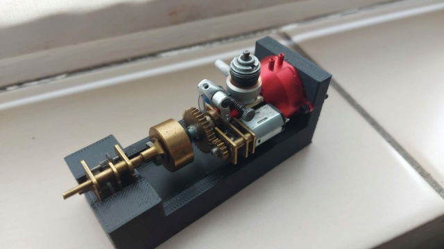
I'm working on a test-stand that will use a 2L. capacity bottle of water for the cooling coil around the cylinder-head.. to see how the engine behaves with a flywheel mounted "no-load" vs. a simulated working-load.
Here's some eye-candy..


The L-bracket on the back of the fixture is for a fuel-cell of some sort. Not sure yet; what that will be...

roddie- Top Poster
-
Posts : 8461
Join date : 2013-07-17
Age : 64
Location : N. Smithfield, Rhode Island -
marine rudder, fins and trim-tabs
![]() roddie Fri May 03, 2024 10:51 pm
roddie Fri May 03, 2024 10:51 pm
This will work for the Roddie-Rigger..

roddie- Top Poster
-
Posts : 8461
Join date : 2013-07-17
Age : 64
Location : N. Smithfield, Rhode Island -
getting back to the sponsons..
![]() roddie Sun May 05, 2024 11:27 pm
roddie Sun May 05, 2024 11:27 pm
The bare "tub" with booms/sponsons is pretty light..


The sponsons are made from 1.5" "Ultraboard" a sign-grade foamboard faced both sides with .015" Polystyrene. So they're 1.5" wide.. which is what the skins need to be. The "sides" have the .015" Polystyrene facers. The Top & Bottom are exposed-foam that needs to be skinned.
I'm "going with" another sign-shop material that I had on hand.. which is .018" phenolic sheet. The sponsons measure 8.0" long on the top.. which is flat. The bottom skin needs to be longer at 8.312" because of the upward-sweep running from the step... to the up-swept front tip. I laid out skins for both; 60 & 90 degree versions. Eight strips @ 1.5" wide.

It's been coiled tightly........

roddie- Top Poster
-
Posts : 8461
Join date : 2013-07-17
Age : 64
Location : N. Smithfield, Rhode Island -
Steamed skins
![]() roddie Wed May 08, 2024 12:21 am
roddie Wed May 08, 2024 12:21 am

I've got a plan for applying the skins.. but I'm using sacrificial sponsons in case it doesn't pan-out. I threw together a paint fixture which has rods that key into the two boom sockets.

I foam-brushed-on KILZ2

The weather here in Northern Rhode Island was superb today. I spent several mid-day hours at the markets. A husband's (retired) chores are never done...
roddie- Top Poster
-
Posts : 8461
Join date : 2013-07-17
Age : 64
Location : N. Smithfield, Rhode Island -
Re: Roddie-Rigger.. a 2005 original design
![]() getback Wed May 08, 2024 7:31 am
getback Wed May 08, 2024 7:31 am

getback- Top Poster
-
Posts : 10279
Join date : 2013-01-18
Age : 66
Location : julian , NC
Re: Roddie-Rigger.. a 2005 original design
![]() roddie Wed May 08, 2024 8:04 pm
roddie Wed May 08, 2024 8:04 pm
getback wrote:Interesting , yes the weather was nice here to today going for hot thought at 88F ! Then a cool down . If can get caught up on old man chores may spray some dope to day ?! Glad you got sometime to work on the outrigger !
Thanks Brother. It was good to chat with you on the telephone. I find these days; that I'm more anxious to prove things. It must show here.. in my posts. Yea.. later on that..
So.. after scratching my head bloody; searching for info. on contact-adhesives that wouldn't degrade my polystyrene foam.
I decided to go with a Gorilla Glue product.. but it's not a liquid.


That's a "scrap" (sacrificial) foam sponson that I used for this experiment. I've used double-sided tape before.. and it works quite well for certain applications. The Gorilla variety is 1.4 inches width. My sponsons are 1.5 inches wide. Adhering the tape-strips along the top and bottom "skins" worked out well. There's room for slight misalignment with the tape-strip without going over the edge.
The Kilz2 that I foam-brushed onto the bare foam sections of the sponson was dry when I checked it 12 hours later. I feel that this application gives the d/s tape more to stick to. I'll seal the edges/seams with an acrylic caulk prior to painting. The main issue was getting the skins to "stick" instantly.. and that's working.
roddie- Top Poster
-
Posts : 8461
Join date : 2013-07-17
Age : 64
Location : N. Smithfield, Rhode Island -
Re: Roddie-Rigger.. a 2005 original design
![]() roddie Fri May 10, 2024 12:52 pm
roddie Fri May 10, 2024 12:52 pm
I put together a painting fixture.. and prepared X2 sets of skins with the Gorilla D/S tape.


The sponsons are designed to easily and quickly slide on and off the booms and are held captive by little hitch-pins. The booms consist of X2 7/32" aluminum tubes of 9.5" length, which slide-through captive 1/4" aluminum tubes in the tub and sponsons. There are also 1/4" alum. spacer-tubes that "slide-on" between the tub and sponsons. I designed the system around the 1.5" width of the sponson material.. and made the tub 3.0" wide with a 1.5" (spacer-tubes) between the tub and sponsons.. for an overall width of 9.0". The booms are 9.5" long to accommodate a flat-washer/hitch-pin retention system.
It's a lightweight arrangement that can be completely disassembled if a part gets damaged.

Last edited by roddie on Fri May 10, 2024 6:57 pm; edited 1 time in total (Reason for editing : added a photo)
roddie- Top Poster
-
Posts : 8461
Join date : 2013-07-17
Age : 64
Location : N. Smithfield, Rhode Island -
Re: Roddie-Rigger.. a 2005 original design
![]() roddie Fri Jun 07, 2024 6:46 pm
roddie Fri Jun 07, 2024 6:46 pm
roddie- Top Poster
-
Posts : 8461
Join date : 2013-07-17
Age : 64
Location : N. Smithfield, Rhode Island -
Re: Roddie-Rigger.. a 2005 original design
![]() rsv1cox Fri Jun 07, 2024 7:35 pm
rsv1cox Fri Jun 07, 2024 7:35 pm
roddie wrote:I just read my last post.... and thought.... Jeeee... why would anyone else want to know that...
Lot's of numbers there roddie, but some here are number people.
Jeeee... why would anyone else want to know that...
I wonder that about all my threads roddie.
rsv1cox- Top Poster
-
Posts : 10851
Join date : 2014-08-18
Location : West Virginia
Re: Roddie-Rigger.. a 2005 original design
![]() MauricioB Sat Jun 08, 2024 12:31 pm
MauricioB Sat Jun 08, 2024 12:31 pm

MauricioB- Top Poster
- Posts : 3649
Join date : 2016-02-16
Age : 53
Location : ARG
Re: Roddie-Rigger.. a 2005 original design
![]() rdw777 Sat Jun 08, 2024 4:19 pm
rdw777 Sat Jun 08, 2024 4:19 pm


rdw777- Diamond Member

-
Posts : 1470
Join date : 2021-03-11
Location : West Texas
Re: Roddie-Rigger.. a 2005 original design
![]() davidll1984 Sun Jun 09, 2024 9:06 am
davidll1984 Sun Jun 09, 2024 9:06 am
I have no doubt that the glue you use is good but for the foam I use thisroddie wrote:getback wrote:Interesting , yes the weather was nice here to today going for hot thought at 88F ! Then a cool down . If can get caught up on old man chores may spray some dope to day ?! Glad you got sometime to work on the outrigger !
Thanks Brother. It was good to chat with you on the telephone. I find these days; that I'm more anxious to prove things. It must show here.. in my posts. Yea.. later on that..
So.. after scratching my head bloody; searching for info. on contact-adhesives that wouldn't degrade my polystyrene foam.There's so much contradictory info. out there.
I decided to go with a Gorilla Glue


davidll1984- Diamond Member
- Posts : 2303
Join date : 2020-02-12
Age : 39
Location : shawinigan
Re: Roddie-Rigger.. a 2005 original design
![]() roddie Sun Jun 09, 2024 1:34 pm
roddie Sun Jun 09, 2024 1:34 pm
Little by little.. I'm getting things put together.. and/or sourcing what I need to get things put together..
I drilled/tapped 5-40/UNC some 2mm couplers to accept a 5-40 stub-shaft on the input (engine) side... and the 2mm stainless steel bike spokes for a wire-drive on the couplers' output side. It's helpful to have 5-40 tap/die in your Cox toolbox.

I drilled a .063" cross-hole in one of the couplings to accept a piece of .062" music-wire as a "wrench" for tightening a 5-40 hex-nut.

Here's an alternate view of the rudder, from a kit that I sourced through Amazon. The white PVC block was something I had in my boat parts-box.. and will provide extra clearance behind the propeller. This will allow the rudder to be mounted on the center-line of the hull.


Last edited by roddie on Sun Jun 09, 2024 1:44 pm; edited 1 time in total (Reason for editing : added a photo)
roddie- Top Poster
-
Posts : 8461
Join date : 2013-07-17
Age : 64
Location : N. Smithfield, Rhode Island -
Re: Roddie-Rigger.. a 2005 original design
![]() roddie Mon Jul 01, 2024 2:13 pm
roddie Mon Jul 01, 2024 2:13 pm
I rattle-can painted some samples.. in the same colors as my last airplane model..

I like these colors. They remind me of "old time" days.. if you catch my drift..
So; over the last few days.. I've been trying to fit-up some drive-line hardware.. including "directional-control" (rudder
The rudder I sourced through Amazon. It was part of a replacement "kit" for a FT012 RC model boat that they offer(ed). There was considerable "slop" where it pivots.. that couldn't be corrected without adding a shim. The assy. unscrews.. so I was able to squeeze a poly-carbonate flat-washer in between and reassemble. It's so easy to make your own flat-washers in the small sizes that we use. I drill then punch* them (*1/4" round) from sheet-plastic. Thin stuff; obviously for making a shim. I already had a shim on-hand, which firmed-up the joint. Being a plastic flat-washer.. it won't rust.

This rudder-blade runs DEEP. The transom on my rigger is only 1.5" above the tub. The rudder-mount was lengthened for more propeller-clearance.

The rudder descends 2.5" below the pivot-point.

There's no kick-back joint. If there's debris in the water.. something's gonna break.
We'll see.. I decided to mount a 1/8" brass water pick-up tube on the backside of the rudder-blade. The 1/8" brass tube was unused from a little Sullivan clunk-tank kit. I cut the 45 with my Dremel..


The brass pick-up tube is "taped-on" for test.
The transom set-up will determine whether this design will work. My drive's depth/angle will not be adjustable. It's not a "flex"-drive.. and there's no "U-joint". I figured that there's less chances of imbalance.
Here's another image of how I drill-through my coupling for inserting a .062" diameter "rod" (as a wrench) to allow tightening/loosening the 5-40 hex-nut.


The below image shows the unused parts from the FT012 rudder-kit. I'd like to think that I could utilize one of those for a turn fin on the inside sponson. (wishful thinking that I'll need one..)

roddie- Top Poster
-
Posts : 8461
Join date : 2013-07-17
Age : 64
Location : N. Smithfield, Rhode Island -
Re: Roddie-Rigger.. a 2005 original design
![]() rsv1cox Tue Jul 02, 2024 3:51 pm
rsv1cox Tue Jul 02, 2024 3:51 pm
rsv1cox- Top Poster
-
Posts : 10851
Join date : 2014-08-18
Location : West Virginia
Re: Roddie-Rigger.. a 2005 original design
![]() rdw777 Tue Jul 02, 2024 5:44 pm
rdw777 Tue Jul 02, 2024 5:44 pm
rdw777- Diamond Member
-
Posts : 1470
Join date : 2021-03-11
Location : West Texas
Re: Roddie-Rigger.. a 2005 original design
![]() getback Thu Jul 04, 2024 7:32 am
getback Thu Jul 04, 2024 7:32 am

getback- Top Poster
-
Posts : 10279
Join date : 2013-01-18
Age : 66
Location : julian , NC
Re: Roddie-Rigger.. a 2005 original design
![]() roddie Fri Jul 05, 2024 4:24 pm
roddie Fri Jul 05, 2024 4:24 pm
Quality work roddie. I like those colors, I have used them together a lot.
by rdw777 on Tue Jul 02, 2024 5:44 pm
I like those colors too….They work good at a distance as well….. Depending on the light, sometimes one is more visible than the other….
by getback on Thu Jul 04, 2024 7:32 am
Glad you got some time to get back to this project colors are a nice blend , looking forward to some test runs ..
Thanks all, for your comments.
The photo below shows engine mount components (Bee engine) that I may not use.. but I really should.. because I made a bunch of them.. as I did with all the other main parts of this rigger. Having access to the CNC router and CAD.. made it quick and easy to make parts in bulk.. and I didn't have to pay for any of the materials.


I had designed (CNC) a "modular" system of PVC and polycarbonate components to utilize the Cox .049 Babe Bee engine, with its 5cc tank-bowl modified for an external fuel-cell and the use of the "Ace" (Ralph Cooney designed) venturi plunger-needle throttle and my muffler design.
The engine-mount is a 3-pc. arrangement consisting of a 3" X 3" 13mm thickness PVC base, routered-out to receive a vertical engine plate which has the Bee's 4-hole mounting pattern and central "thru-bore" (guide) for the .062" dia. Ace needle to pass through and into the engine's air-intake. The 3rd piece is an offset PVC "post" for a polycarbonate throttle-horn/bellcrank. PVC cement is used to glue that assembly together. There's also a pair of optional PVC "wedges" to angle the entire mount assembly to allow exiting the transom deeper.. if need be.


Below; a couple of engine prototypes that would use the Ace throttle.


There's a LOT of foam components for building the hull and sponsons.

Craziness I know.. but I had thoughts of possibly kitting these, back when I made all the pieces.
roddie- Top Poster
-
Posts : 8461
Join date : 2013-07-17
Age : 64
Location : N. Smithfield, Rhode Island -
Re: Roddie-Rigger.. a 2005 original design
![]() rsv1cox Fri Jul 05, 2024 7:34 pm
rsv1cox Fri Jul 05, 2024 7:34 pm
rsv1cox- Top Poster
-
Posts : 10851
Join date : 2014-08-18
Location : West Virginia
Page 1 of 2 • 1, 2 ![]()
» New P-38 profile scratch build log
» Another proposed design by Roddie
» Anyone knows this design?
» Roddie, You out there?