

 Rules
Rules
Log in
Search
Latest topics
» Fox .35 Modifications by Onelife Today at 9:18 pm
» Happy Anzac Day!
by 706jim Today at 6:44 pm
» Project Cox .049 r/c & Citabrian Champion
by MauricioB Today at 4:08 pm
» Jim Walkers FireBee - This is going to be fun
by rsv1cox Today at 3:56 pm
» Revivng Some Childhood Classics
by rsv1cox Today at 7:17 am
» Introducing our Cox .049 TD Engines
by getback Today at 6:20 am
» Roddie's flat-bottomed boat..
by Levent Suberk Today at 12:23 am
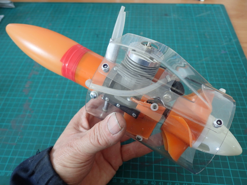
» Cox powered jet-pump for model Sprint Boat
by roddie Yesterday at 10:25 pm
» Micro Draco Gets to Fly on a Beautiful Morning.
by rdw777 Yesterday at 8:15 pm
» Jim Walker Firebaby
by rdw777 Yesterday at 8:06 pm
» Hydro-bat by Vic Smeed: engine probs
by GallopingGhostler Yesterday at 5:12 pm
» Roddie-Rigger.. a 2005 original design
by roddie Yesterday at 3:39 pm
Cox Engine of The Month

CEF Traveling Engine

Win This Engine!

Live on Patrol


PS: What is that?
Page 1 of 1

PS: What is that?
![]() flyjsh Tue Oct 21, 2014 1:51 pm
flyjsh Tue Oct 21, 2014 1:51 pm
Is it a cricket bat?
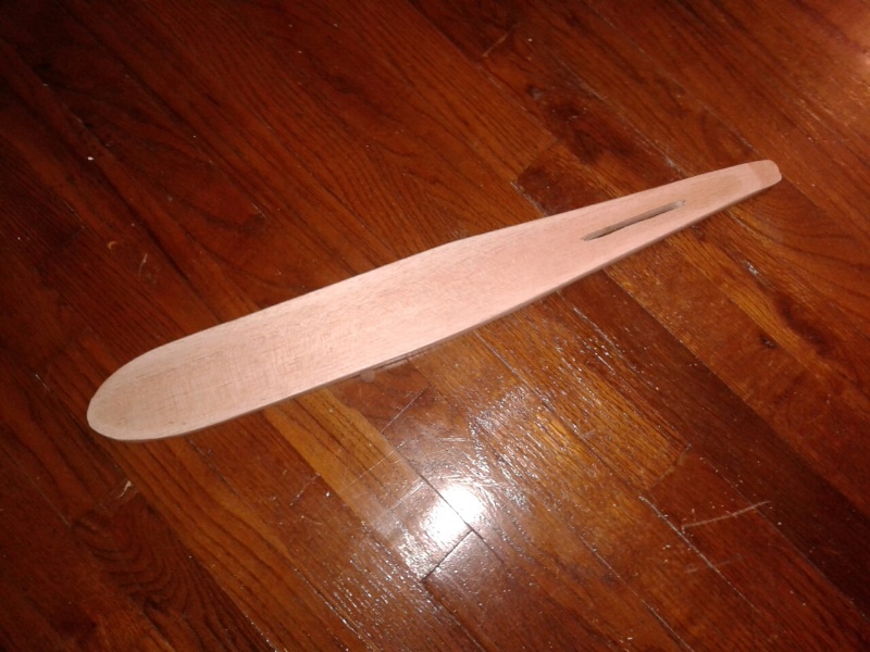
Perhaps a mock up of for a new submarine....
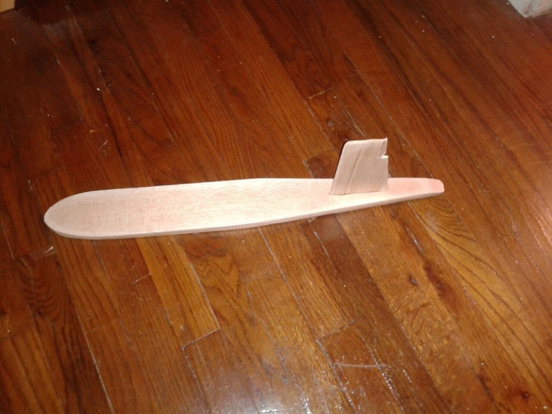
Ooops, upside down, errr ummm, the view from below
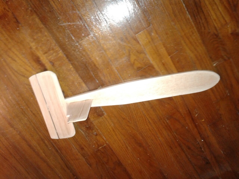
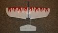
Maybe an airplane? (Flying inverted)
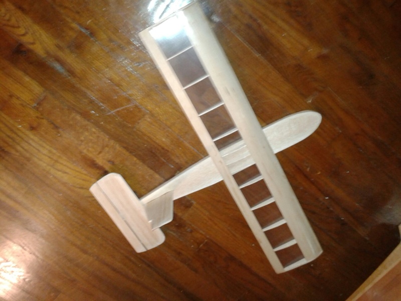
Yes, indeed, it is an airplane: the P.S. aka The Prop Saver. I found the plans on Outerzone http://www.outerzone.co.uk/plan_details.asp?ID=2713
I made a few changes. First off, being a solo flyer, I added tundra tires. Wanting to make it easier to store, I used rubber band mounting for the wings, and pegged the vertical stab. If the plane flies well, I can make additional stabs and mounts that I can swap in the field and voilà!, a flying test bed!

Perhaps a mock up of for a new submarine....
Ooops, upside down,
Maybe an airplane? (Flying inverted)
Yes, indeed, it is an airplane: the P.S. aka The Prop Saver. I found the plans on Outerzone http://www.outerzone.co.uk/plan_details.asp?ID=2713
I made a few changes. First off, being a solo flyer, I added tundra tires. Wanting to make it easier to store, I used rubber band mounting for the wings, and pegged the vertical stab. If the plane flies well, I can make additional stabs and mounts that I can swap in the field and voilà!, a flying test bed!

flyjsh- Gold Member

- Posts : 129
Join date : 2013-03-12
Location : Houston, Texas

pkrankow- Top Poster

- Posts : 3025
Join date : 2012-10-02
Location : Ohio
Re: PS: What is that?
![]() flyjsh Tue Oct 21, 2014 2:24 pm
flyjsh Tue Oct 21, 2014 2:24 pm
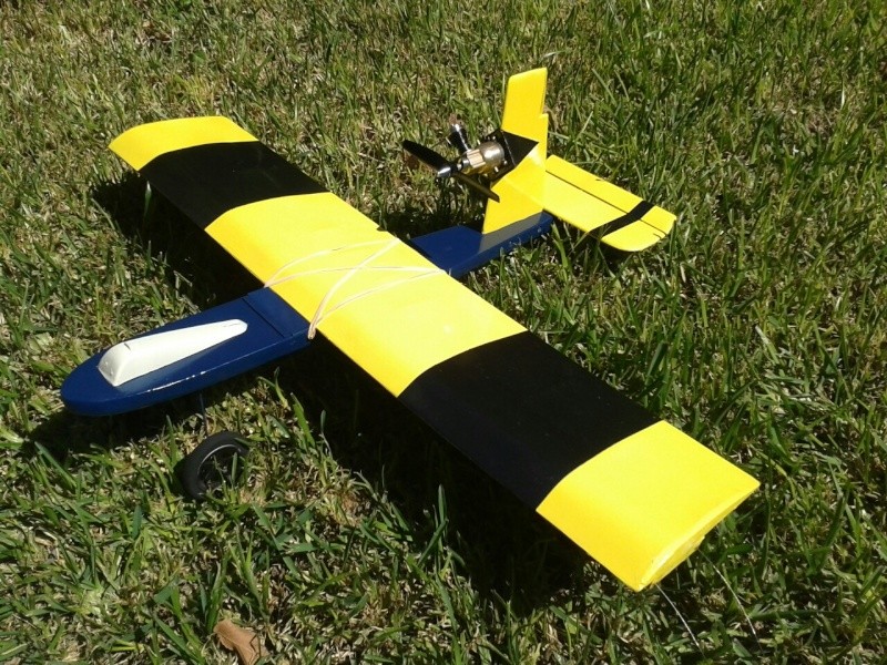
I don't know yet, but I am betting better than I do  I need to get some lead under the canopy: with the engine placement, it builds tail heavy.
FYI, the canopy is cut from the "shoulder" of a Sea Breeze bottle http://www.seabreezeclean.com/
FYI, the canopy is cut from the "shoulder" of a Sea Breeze bottle http://www.seabreezeclean.com/
flyjsh- Gold Member
- Posts : 129
Join date : 2013-03-12
Location : Houston, Texas
Re: PS: What is that?
![]() flyjsh Tue Oct 21, 2014 7:27 pm
flyjsh Tue Oct 21, 2014 7:27 pm
So much for the flying testbed idea.  An unproven plane, unproven engine, and a marginal pilot: me trying to find level, engine hiccups, power on smash and go, and the stab rips out. The small area of the two dowels I used was insufficient, and they ripped clean out the bottom of the stab. Only cosmetic and field reparable damage otherwise.
The article sad it would be heavy and slow, and from that short flight I agree.
An unproven plane, unproven engine, and a marginal pilot: me trying to find level, engine hiccups, power on smash and go, and the stab rips out. The small area of the two dowels I used was insufficient, and they ripped clean out the bottom of the stab. Only cosmetic and field reparable damage otherwise. The article sad it would be heavy and slow, and from that short flight I agree.
flyjsh- Gold Member
- Posts : 129
Join date : 2013-03-12
Location : Houston, Texas
Re: PS: What is that?
![]() Cribbs74 Tue Oct 21, 2014 7:43 pm
Cribbs74 Tue Oct 21, 2014 7:43 pm
If at first you don't succeed...
Hey, at least you tried. Glue it up, fix the problems and go again!
Ron
Hey, at least you tried. Glue it up, fix the problems and go again!
Ron

Cribbs74- Moderator


Posts : 11895
Join date : 2011-10-24
Age : 50
Location : Tuttle, OK
Re: PS: What is that?
![]() roddie Tue Oct 21, 2014 8:11 pm
roddie Tue Oct 21, 2014 8:11 pm
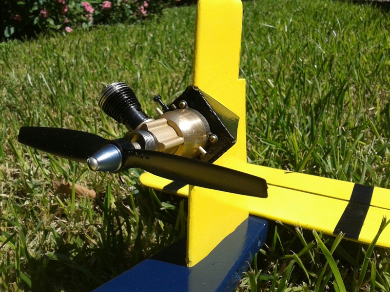
That's a radical engine mount! I like the 45 degree "diamond" look. Fairing that back; as geometrically neat as it looks, must have taken some time. Does the plan specify this?
IMHO... that vertical-stab/engine pylon.. needs to have some "integrity". Maybe glassing would help.. but that fin needs to be mounted rigidly to the fuse. The weight of the engine dictates the strength of the mount. Maybe 1/8" birch-ply epoxied into a fuse-slot.. and/or gluing-in square-stock rails either-side of the joint for support would help prevent separation when stressed.
Did the model seem "controllable" at any point? Could the wing saddle be moved back any.. With that fuse.. you have a lot of options/area to try to incorporate "rails" into the wing-attachment.. and hook & loop mating-surfaces, to lock any lateral movement for dialing-in the ultimate CG. The rubber-band attachment-system is still desirable. With the aid of rails.. and the hook & loop's ability to "hold" a linear position.. it takes some of the stress off a "rubber-band only" style of mount.

roddie- Top Poster
- Posts : 8268
Join date : 2013-07-17
Age : 64
Location : N. Smithfield, Rhode Island -

Re: PS: What is that?
![]() flyjsh Tue Oct 21, 2014 10:15 pm
flyjsh Tue Oct 21, 2014 10:15 pm
roddie wrote:That's a radical engine mount! I like the 45 degree "diamond" look. Fairing that back; as geometrically neat as it looks, must have taken some time. Does the plan specify this?
IMHO... that vertical-stab/engine pylon.. needs to have some "integrity". Maybe glassing would help.. but that fin needs to be mounted rigidly to the fuse. The weight of the engine dictates the strength of the mount. Maybe 1/8" birch-ply epoxied into a fuse-slot.. and/or gluing-in square-stock rails either-side of the joint for support would help prevent separation when stressed.
Did the model seem "controllable" at any point? Could the wing saddle be moved back any.. With that fuse.. you have a lot of options/area to try to incorporate "rails" into the wing-attachment.. and hook & loop mating-surfaces, to lock any lateral movement for dialing-in the ultimate CG. The rubber-band attachment-system is still desirable. With the aid of rails.. and the hook & loop's ability to "hold" a linear position.. it takes some of the stress off a "rubber-band only" style of mount.
Yes, the plan uses that mount. I initially thought of scraping it, notching the stab, and mounting a TD, but I thought the model needed that visual element. As to its neatness.... black hides imperfections. I tried to do it exactly as the plans had described, but ended up just eyeballing and sanding.
The fuse is slotted all the way through and the stab inserted. Since I am going to glue it in, I probably will add gussets.
It seemed very nose heavy, but the cg was pretty much spot on. It seemed to have more down authority than up (to be safe, I'll add a guide for the push rod to reduce any flexing). I like the idea of velcro attachment! Never thought of that. Aside from moving the cg (or reducing the amount of ballast), how will shortening the distance between the wing and elevator affect handling? On one hand, it shortens the arm of the elevator giving it less authority. On the other, it seems like it could make it twitchier

flyjsh- Gold Member
- Posts : 129
Join date : 2013-03-12
Location : Houston, Texas
Re: PS: What is that?
![]() flyjsh Tue Oct 21, 2014 10:17 pm
flyjsh Tue Oct 21, 2014 10:17 pm
Cribbs74 wrote:If at first you don't succeed...
Hey, at least you tried. Glue it up, fix the problems and go again!
Ron
Oh, she'll fly again. Except for the stab, I could have field repaired her.
flyjsh- Gold Member
- Posts : 129
Join date : 2013-03-12
Location : Houston, Texas
Re: PS: What is that?
![]() RknRusty Tue Oct 21, 2014 10:23 pm
RknRusty Tue Oct 21, 2014 10:23 pm
1959, eh. There wasn't so much of a box to think outside of back then, so anything could be tried without so many naysayers. Looks aerodynamically feasible to me. If you can get a steady run out of that cantankerous Bee.
Rusty
Rusty
_________________
Don't Panic!
...and never Ever think about how good you are at something...
while you're doing it!
My Hot Rock & Blues Playlist
...and never Ever think about how good you are at something...
while you're doing it!
My Hot Rock & Blues Playlist
RknRusty- Rest In Peace

- Posts : 10869
Join date : 2011-08-10
Age : 68
Location : South Carolina, USA
Re: PS: What is that?
![]() roddie Tue Oct 21, 2014 11:07 pm
roddie Tue Oct 21, 2014 11:07 pm
I thought that being able to adjust the wing fore/aft would allow you to play with the CG without adding weight. This isn't an option with a conventional fixed-saddle/mounting. Yes.. it will change your moment-arm.. but that could be advantageous.
roddie- Top Poster
- Posts : 8268
Join date : 2013-07-17
Age : 64
Location : N. Smithfield, Rhode Island -
Re: PS: What is that?
![]() pkrankow Wed Oct 22, 2014 7:23 am
pkrankow Wed Oct 22, 2014 7:23 am
Is the bell crank in the wing or fuse? If it is in the removable wing I see a few problems if locating pins or some other solid attachment is not used. If it is in the fuse, then an adjustable tip guide might be in order, but the lines should be in the same place with respect to CG so the tip guide is less needed.
Nose heavy models fly poorly, tail heavy models fly once. Start nose heavy.
Phil
Nose heavy models fly poorly, tail heavy models fly once. Start nose heavy.
Phil
pkrankow- Top Poster
- Posts : 3025
Join date : 2012-10-02
Location : Ohio
Page 1 of 1
Permissions in this forum:
You cannot reply to topics in this forum