

 Rules
Rules
by Onelife Today at 9:18 pm
» Happy Anzac Day!
by 706jim Today at 6:44 pm
» Project Cox .049 r/c & Citabrian Champion
by MauricioB Today at 4:08 pm
» Jim Walkers FireBee - This is going to be fun
by rsv1cox Today at 3:56 pm
» Revivng Some Childhood Classics
by rsv1cox Today at 7:17 am
» Introducing our Cox .049 TD Engines
by getback Today at 6:20 am
» Roddie's flat-bottomed boat..
by Levent Suberk Today at 12:23 am
» Cox powered jet-pump for model Sprint Boat
by roddie Yesterday at 10:25 pm
» Micro Draco Gets to Fly on a Beautiful Morning.
by rdw777 Yesterday at 8:15 pm
» Jim Walker Firebaby
by rdw777 Yesterday at 8:06 pm
» Hydro-bat by Vic Smeed: engine probs
by GallopingGhostler Yesterday at 5:12 pm
» Roddie-Rigger.. a 2005 original design
by roddie Yesterday at 3:39 pm


CEF speed contest Design Discussions (2014)
Page 5 of 20 •  1, 2, 3, 4, 5, 6 ... 12 ... 20
 ![]()
Re: CEF speed contest Design Discussions (2014)
![]() pkrankow Mon Aug 18, 2014 11:04 pm
pkrankow Mon Aug 18, 2014 11:04 pm
RknRusty wrote:Theo
I sanded a similar foil on the inboard side of the fin on my Baby Flite Streak. The outboard of the fin was left flat.That was intended to cause the air flowing over the curve to form a vacuum and theoretically pull the tail into the circle resulting in a slightly helpful outward yaw.
Yours is nicely shaped but i can only see the curved outboard side of the fin. Unless there is an equal foil on the inboard side, this rudder is going to yaw the tail out and the nose into the circle. Am I missing something? It wouldn't be the first time.
Rusty
That is surprisingly easy to screw up Rusty. I have had to remake parts over that simple error.
Phil

pkrankow- Top Poster

- Posts : 3025
Join date : 2012-10-02
Location : Ohio
Re: CEF speed contest Design Discussions (2014)
![]() Cribbs74 Mon Aug 18, 2014 11:10 pm
Cribbs74 Mon Aug 18, 2014 11:10 pm

Cribbs74- Moderator


Posts : 11895
Join date : 2011-10-24
Age : 50
Location : Tuttle, OK
Re: CEF speed contest Design Discussions (2014)
![]() Theo Kleynhans Tue Aug 19, 2014 12:55 am
Theo Kleynhans Tue Aug 19, 2014 12:55 am
Rusty, Thank you for the info on the Rudder. Yes it is sanded on both sides. So it should be the same. But I will ensure that it is not sanded more on the outboard side.
Theo

Theo Kleynhans- Gold Member

- Posts : 196
Join date : 2013-12-30
Age : 42
Location : South Africa
Re: CEF speed contest Design Discussions (2014)
![]() RknRusty Tue Aug 19, 2014 1:34 am
RknRusty Tue Aug 19, 2014 1:34 am
Okay good. Just thought I better check. Now another question, being an active component in the airflow, would not there be some drag associated with an airfoil? For speed vs stability, would not a razor edged flat fin that slices straight through the air with little disturbance be faster? I would assume the same of the stab.Theo Kleynhans wrote:Thank you all for the kind words guys. Much appreciated. I am really learning as I go along.
Rusty, Thank you for the info on the Rudder. Yes it is sanded on both sides. So it should be the same. But I will ensure that it is not sanded more on the outboard side.
Theo
Rusty
_________________
...and never Ever think about how good you are at something...
while you're doing it!
My Hot Rock & Blues Playlist
RknRusty- Rest In Peace

- Posts : 10869
Join date : 2011-08-10
Age : 68
Location : South Carolina, USA
Re: CEF speed contest Design Discussions (2014)
![]() Theo Kleynhans Tue Aug 19, 2014 4:01 am
Theo Kleynhans Tue Aug 19, 2014 4:01 am
I must say I am not an expert in this field, but I did also raise the question to my mentor and teacher Keith Renecle before starting my build.
He said that a wing with an airfoil is faster than a flat sheet wing. I unfortunately do not know why?? Thus I made the airfoil.
I hope someone that knows the reasoning can help us??
Theo
Theo Kleynhans- Gold Member
- Posts : 196
Join date : 2013-12-30
Age : 42
Location : South Africa
Re: CEF speed contest Design Discussions (2014)
![]() roddie Tue Aug 19, 2014 5:50 am
roddie Tue Aug 19, 2014 5:50 am
Theo Kleynhans wrote:Hi Rusty
I must say I am not an expert in this field, but I did also raise the question to my mentor and teacher Keith Renecle before starting my build.
He said that a wing with an airfoil is faster than a flat sheet wing. I unfortunately do not know why?? Thus I made the airfoil.
I hope someone that knows the reasoning can help us??
Theo
I'll take a "stab" at it.. to say that a wing that doesn't generate any "lift" or the stability of even a fully symmetrical airfoil.. is going to cause drag. The negative pressure behind an air-foiled wing's trailing-edge I think actually "starts" at some point chord-wise.. close to the C of G.. reducing the area of friction rearward, as the air flows over/under. I'm probably totally wrong...
But I won't stop there.. a "flat" wing is merely a deflective surface. It's not helping to "suspend" the craft in the air.. and thus requires the shear power of the engine to maintain flight.

roddie- Top Poster
- Posts : 8268
Join date : 2013-07-17
Age : 64
Location : N. Smithfield, Rhode Island -

Re: CEF speed contest Design Discussions (2014)
![]() Oldenginerod Tue Aug 19, 2014 6:36 am
Oldenginerod Tue Aug 19, 2014 6:36 am
An aerofoiled (the way we of British decent say it) wing with a flat bottom should generate lift with the leading and trailing edges exactly harizontal, so the "thickness" of the wing is only the thickness of the wing.
 Well, I know what I mean.
In this way, I can see why a flat wing, even if very thin, would create more drag.
Rod.

Oldenginerod- Top Poster
- Posts : 3970
Join date : 2012-06-15
Age : 61
Location : Drouin, Victoria
Re: CEF speed contest Design Discussions (2014)
![]() RknRusty Tue Aug 19, 2014 7:21 am
RknRusty Tue Aug 19, 2014 7:21 am
Rod and Roddie, I understand, but what about the tail fin in question. Is it that a flat blade will "hunt," bouncing back and forth while doing its job of stabilizing the yaw of the plane, thus inducing drag with each bounce? Whereas an airfoil will be more stable being surrounded by a cushion of air and buffered from such disorderly oscillating? I'm Waaay out of my knowledge base here, so I'm guessing and making it up as I go.
The fact that the plane is flying through the air while constantly being dragged off course by the control lines may play into an asymmetrical foil on the rudder, slightly thicker on the outboard side to accommodate less drag for the circular path. Well hell, maybe I've just answered my question. Maybe we actually do want a slight yaw-in on a speed ship. I'm in even deeper now.
Rusty
_________________
...and never Ever think about how good you are at something...
while you're doing it!
My Hot Rock & Blues Playlist
RknRusty- Rest In Peace
- Posts : 10869
Join date : 2011-08-10
Age : 68
Location : South Carolina, USA
Re: CEF speed contest Design Discussions (2014)
![]() RknRusty Tue Aug 19, 2014 7:57 am
RknRusty Tue Aug 19, 2014 7:57 am
Rusty
_________________
...and never Ever think about how good you are at something...
while you're doing it!
My Hot Rock & Blues Playlist
RknRusty- Rest In Peace
- Posts : 10869
Join date : 2011-08-10
Age : 68
Location : South Carolina, USA
Re: CEF speed contest Design Discussions (2014)
![]() pkrankow Tue Aug 19, 2014 8:20 am
pkrankow Tue Aug 19, 2014 8:20 am
RknRusty wrote:Eureka! Did I just get that right? We want the speed plane to yaw in slightly for the sake of reduced drag, unlike a sport plane. Seems like a no brainer now.
Rusty
er...as long as the yaw in is less than the required turn for the circle...I think having a straight line or even yaw out might be more appropriate than yaw in. Lines tight and all.
Phil
pkrankow- Top Poster
- Posts : 3025
Join date : 2012-10-02
Location : Ohio
Re: CEF speed contest Design Discussions (2014)
![]() ian1954 Tue Aug 19, 2014 8:41 am
ian1954 Tue Aug 19, 2014 8:41 am


Some only have half a wing and tailplane!


ian1954- Diamond Member

- Posts : 2688
Join date : 2011-11-16
Age : 69
Location : England
Re: CEF speed contest Design Discussions (2014)
![]() JPvelo Tue Aug 19, 2014 10:04 am
JPvelo Tue Aug 19, 2014 10:04 am
I wasn't going to divulge any secrets but.... That's why my plane has the rudder air foiled on the outboard side, no tip wieght, and leadouts above the vertical cg that can be moved forward of the horizontal cg. I want it to fly in a counter clockwise circle and rely on centrifugal force to keep the lines tight. Or it may just fly into the center of the circle and try to kill me.RknRusty wrote: Well hell, maybe I've just answered my question. Maybe we actually do want a slight yaw-in on a speed ship. I'm in even deeper now.
Rusty

Jim

JPvelo- Diamond Member
- Posts : 1972
Join date : 2011-12-02
Age : 56
Location : Colorado
Re: CEF speed contest Design Discussions (2014)
![]() Mike Mulligan Tue Aug 19, 2014 1:29 pm
Mike Mulligan Tue Aug 19, 2014 1:29 pm
JPvelo wrote:I wasn't going to divulge any secrets but.... That's why my plane has the rudder air foiled on the outboard side, no tip wieght, and leadouts above the vertical cg that can be moved forward of the horizontal cg. I want it to fly in a counter clockwise circle and rely on centrifugal force to keep the lines tight. Or it may just fly into the center of the circle and try to kill me.RknRusty wrote: Well hell, maybe I've just answered my question. Maybe we actually do want a slight yaw-in on a speed ship. I'm in even deeper now.
Rusty
Jim
Wow Jim, if you don't mind me saying, it sounds like you're inviting some pretty rowdy guests to your party...
Keep in mind that on 42 foot lines the difference between perpendicular at the leadouts and perpendicular at the fin (say, 8" aft) is less than half a degree. Even if you did the maths and set the fin exactly perpendicular to the center of the circle, a very slight yaw could cause it to go from neutral to a left (or right) turn moment rather quickly!
Also, the fin isn't just operating in clear air as it moves around the circle. It is subject to the wind (if any) shifting 360 degrees each lap and is also operating in the swirling wash of the propeller. With a right-hand prop the wash swirls in a spiral around the fuse ultimately hitting the fin on the left side causing a tendency to veer to the left. That is why several of the Proto-speed designs put the fin on the bottom of the fuse where that same swirl effect tends to cause a right turn. Even full size single engine airplanes have the fin rigged with a slight offset to help compensate for this effect. Of course with a left-hand prop the effect is reversed and works FOR us in a counter-clockwise circle.
Combine all that with high leadouts (inward rolling moment), no tip weight, leadouts forward of the CG and it all sounds a bit too much.
Of course, you are a pretty sharp guy and have probably thought of all this already, so I can't wait to see what you are REALLY up to!
Still, wear a helmet please...
Mike

Mike Mulligan- Gold Member
- Posts : 103
Join date : 2014-06-08
Age : 60
Location : Vista CA (Near San Diego) -
Re: CEF speed contest Design Discussions (2014)
![]() roddie Tue Aug 19, 2014 6:49 pm
roddie Tue Aug 19, 2014 6:49 pm
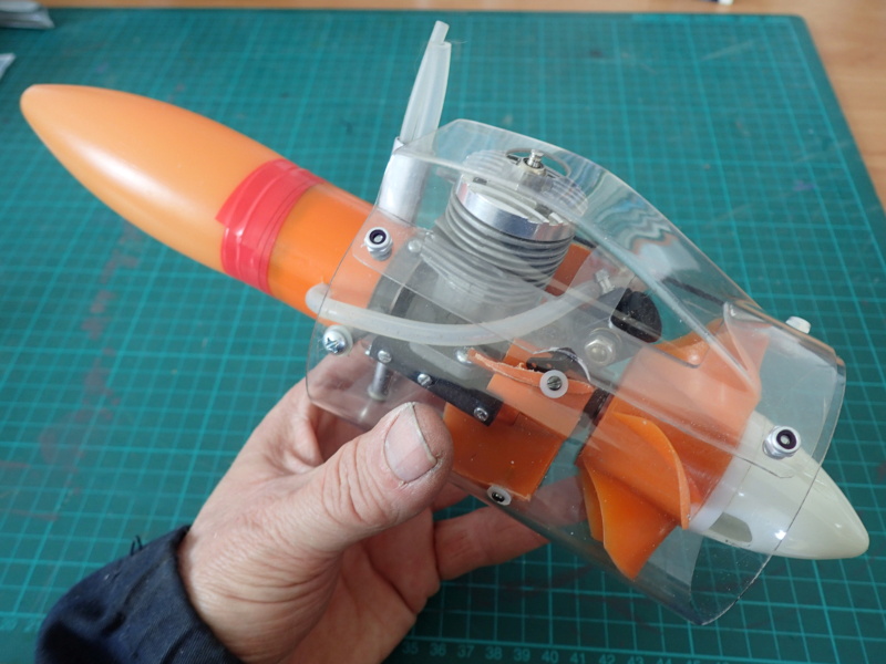
This is the model..

This pic shows the adjustable rudder deflected.

I think I may have lost some reputation points by posting this..

roddie- Top Poster
- Posts : 8268
Join date : 2013-07-17
Age : 64
Location : N. Smithfield, Rhode Island -
Re: CEF speed contest Design Discussions (2014)
![]() Cribbs74 Tue Aug 19, 2014 6:59 pm
Cribbs74 Tue Aug 19, 2014 6:59 pm
Cribbs74- Moderator
-
Posts : 11895
Join date : 2011-10-24
Age : 50
Location : Tuttle, OK
Re: CEF speed contest Design Discussions (2014)
![]() roddie Tue Aug 19, 2014 9:02 pm
roddie Tue Aug 19, 2014 9:02 pm
Cribbs74 wrote:Not by posting, just because you never flew it...
Never flew it "successfully" Ron.. look at the crack in the fuse behind the firewall, extending back to the leading edge of the wing.
roddie- Top Poster
- Posts : 8268
Join date : 2013-07-17
Age : 64
Location : N. Smithfield, Rhode Island -
Re: CEF speed contest Design Discussions (2014)
![]() Cribbs74 Tue Aug 19, 2014 9:10 pm
Cribbs74 Tue Aug 19, 2014 9:10 pm
Cribbs74- Moderator
-
Posts : 11895
Join date : 2011-10-24
Age : 50
Location : Tuttle, OK
Re: CEF speed contest Design Discussions (2014)
![]() roddie Tue Aug 19, 2014 9:23 pm
roddie Tue Aug 19, 2014 9:23 pm
Cribbs74 wrote:I see, I was only pulling your leg. I gave you a + rep point for posting.
a "pitty-point"...
roddie- Top Poster
- Posts : 8268
Join date : 2013-07-17
Age : 64
Location : N. Smithfield, Rhode Island -
Re: CEF speed contest Design Discussions (2014)
![]() Theo Kleynhans Wed Aug 20, 2014 1:53 am
Theo Kleynhans Wed Aug 20, 2014 1:53 am
All of this talk regarding the rudder and airfoils is a lot to take in.
I have another question regarding engine position. If you have a look at the picture below of the Nemesis, you will see that the engine/prop is not situated in the middle vertically at the nose. It is actually higher than the centre line of the nose. Can I mount my engine the same way? Higher up like the drawing. Will this make a difference?

Theo
Theo Kleynhans- Gold Member
- Posts : 196
Join date : 2013-12-30
Age : 42
Location : South Africa
Re: CEF speed contest Design Discussions (2014)
![]() batjac Wed Aug 20, 2014 12:18 pm
batjac Wed Aug 20, 2014 12:18 pm
Theo Kleynhans wrote:That plane of yours looks interesting Roddie. You should maybe try and fly it now that you are experienced.
All of this talk regarding the rudder and airfoils is a lot to take in.
I have another question regarding engine position. If you have a look at the picture below of the Nemesis, you will see that the engine/prop is not situated in the middle vertically at the nose. It is actually higher than the centre line of the nose. Can I mount my engine the same way? Higher up like the drawing. Will this make a difference?
Theo
Theo, the reason the engine in Nemesis is offset like that instead of centerline is because all the fiddly bits of the engine are hanging below the case. The carb and oil pan are down there, so the cowling has to be offset to keep everything nice and tight. I don't know if Nemesis uses an alternator, or just relies on battery power for such short race runs, but there could be electrical system components hanging below the engine, too. I'm sure if they could, Team Nemesis would love to have it centerline with minimal cowling area and drag.
My personal opinion is that it won't make much of a difference for our contest. If you could get your plane 0-0-0 with everything in-line, you'd have less drag on it. But I don't think engine above centerline is really a meaningful concern.
The Blasé Mark

batjac- Diamond Member
-
Posts : 2335
Join date : 2013-05-22
Age : 61
Location : Broken Arrow, OK, USA
Re: CEF speed contest Design Discussions (2014)
![]() Mike Mulligan Wed Aug 20, 2014 12:39 pm
Mike Mulligan Wed Aug 20, 2014 12:39 pm
I just re-read the post I put up regarding Jim's plans, rudders and such and I feel I need to apologize.
When I read it this morning, I felt it came across as somewhat snarky and sarcastic, and that was NOT AT ALL what I intended!
Jim, your planes are very clever, well designed and built. When I said I felt that you are a sharp guy and that I can't wait to see what you are up to, I meant it very sincerely, but the way it was written it could be perceived as being sarcastic. That is in NO WAY what I intended, and if it did come across that way to anyone, especially Jim, I sincerely apologize.
Mike
Mike Mulligan- Gold Member
- Posts : 103
Join date : 2014-06-08
Age : 60
Location : Vista CA (Near San Diego) -
Re: CEF speed contest Design Discussions (2014)
![]() Cribbs74 Wed Aug 20, 2014 1:07 pm
Cribbs74 Wed Aug 20, 2014 1:07 pm
Theo Kleynhans wrote:That plane of yours looks interesting Roddie. You should maybe try and fly it now that you are experienced.
All of this talk regarding the rudder and airfoils is a lot to take in.
I have another question regarding engine position. If you have a look at the picture below of the Nemesis, you will see that the engine/prop is not situated in the middle vertically at the nose. It is actually higher than the centre line of the nose. Can I mount my engine the same way? Higher up like the drawing. Will this make a difference?
Theo
As long as your thrust line stays the same you can mount above or below centerline. It really only poses a problem if you build in up or down thrust .
Cribbs74- Moderator
-
Posts : 11895
Join date : 2011-10-24
Age : 50
Location : Tuttle, OK
Re: CEF speed contest Design Discussions (2014)
![]() pkrankow Wed Aug 20, 2014 1:47 pm
pkrankow Wed Aug 20, 2014 1:47 pm
There is reasonable preference to having everything in line.
Hang your engine inverted and run with it for the scale look.
Phil
pkrankow- Top Poster
- Posts : 3025
Join date : 2012-10-02
Location : Ohio
Re: CEF speed contest Design Discussions (2014)
![]() roddie Wed Aug 20, 2014 7:47 pm
roddie Wed Aug 20, 2014 7:47 pm
pkrankow wrote:
Hang your engine inverted and run with it for the scale look.
Phil
I agree with Phil.. and utilizing the scale "air-scoop" would help when you cowl-in an inverted cylinder. You could put louvers.. or some other venting rearward in your cowl, to scavenge the exhaust-wastes out.. and insure good airflow/cooling of the engine. A side-hole in the cowl for an exhaust-prime might be a good idea to help start the engine. Leave just enough of the glow-head exposed out the bottom to attach your battery clip.
roddie- Top Poster
- Posts : 8268
Join date : 2013-07-17
Age : 64
Location : N. Smithfield, Rhode Island -
Re: CEF speed contest Design Discussions (2014)
![]() pkrankow Wed Aug 20, 2014 9:46 pm
pkrankow Wed Aug 20, 2014 9:46 pm
roddie wrote:pkrankow wrote:
Hang your engine inverted and run with it for the scale look.
Phil
I agree with Phil.. and utilizing the scale "air-scoop" would help when you cowl-in an inverted cylinder. You could put louvers.. or some other venting rearward in your cowl, to scavenge the exhaust-wastes out.. and insure good airflow/cooling of the engine. A side-hole in the cowl for an exhaust-prime might be a good idea to help start the engine. Leave just enough of the glow-head exposed out the bottom to attach your battery clip.
The thumb says minimum 2x the exit area as the intake area for the vents.
Phil
pkrankow- Top Poster
- Posts : 3025
Join date : 2012-10-02
Location : Ohio
Page 5 of 20 • 1, 2, 3, 4, 5, 6 ... 12 ... 20 ![]()
» CEF T-Shirt Design Contest
» *VOTE* CEF T-Shirt Design Contest
» What is it???
» Cox Engine Forum Speed Contest 2018!!!